Warning – Milwaukee Tool 4125 User Manual
Page 9
9
Assembling and Using a Vacuum System
For Cat. No. 4120 only.
7. Tighten the four (4) leveling screws only enough
to eliminate rocking. Over-tightening can lift the
gasket off the ground and release the vacuum.
Leveling
Screws
Vacuum Line
Coupler
Vacuum Adapter Assembly
Fig. 15
Vacuum
Pad
Gasket
Coupler
Vacuum
Release
Valve
Filter Jar
Vacuum
Gauge
Small Hole
for Attaching
Pump to
Dymorig
Stand
Vacuum
Hose
Fig. 14
The vacuum pad is most effective when it is
secured to a relatively smooth surface such as
poured concrete.
If the surface is too porous or rough, the vacuum
pad may not hold securely. Before using the vacu-
um pad, always check the gasket on the underside
of the base to make sure it isn't worn, cracked or
torn. If it is, immediately replace the gasket, oth-
erwise the vacuum may not hold the rig securely.
To replace the gasket, see "Replacing Vacuum
Pad Gaskets" in the "Maintenance" section. See
“Accessories" for gasket part number.
1. Position the rig as required for coring the hole.
2. Loosen the four (4) leveling screws until the ends
are above the bottom surface of the base.
3. Place the vacuum adapter assembly into the slot
in the base.
4. Connect one end of the supplied vacuum hose
to the vacuum line coupler on the vacuum base.
To do this, pull back the collar on the hose and
push the end of the hose onto the coupler until
it snaps into place. Connect the other end of the
vacuum hose to the coupler on the vacuum pump
following the same procedure.
5. The vacuum pump may be set on a dry surface
away from the rig or mounted to the base of the
Dymorig as shown. To mount the vacuum pump
on the base, place the small holes on the vacuum
pump mounting bracket over the two tapped
holes on the base. Attach the vacuum pump to
the base with two (2) 1/4" - 20 screws supplied
in the accessory bag.
6. Plug the vacuum pump into the power source - the
pump will start automatically. Step on the base
until it lowers and adheres to the work surface.
WARNING
The vacuum gauge must
read a minimum of 20 inches of mercury
vacuum. To reduce the risk of injury DO NOT
CORE if the gauge reads less than 20 inches
of mercury vacuum.
Supply an Adequate Water Flow
An adequate supply of water must fl ow freely and
constantly during the entire cut. Dymodrills are
equipped with a built-in water shut-off valve to al-
low water to fl ow down the inside and up around
the outside of the bit. This acts to cool the bit and
fl ush cuttings from the hole.
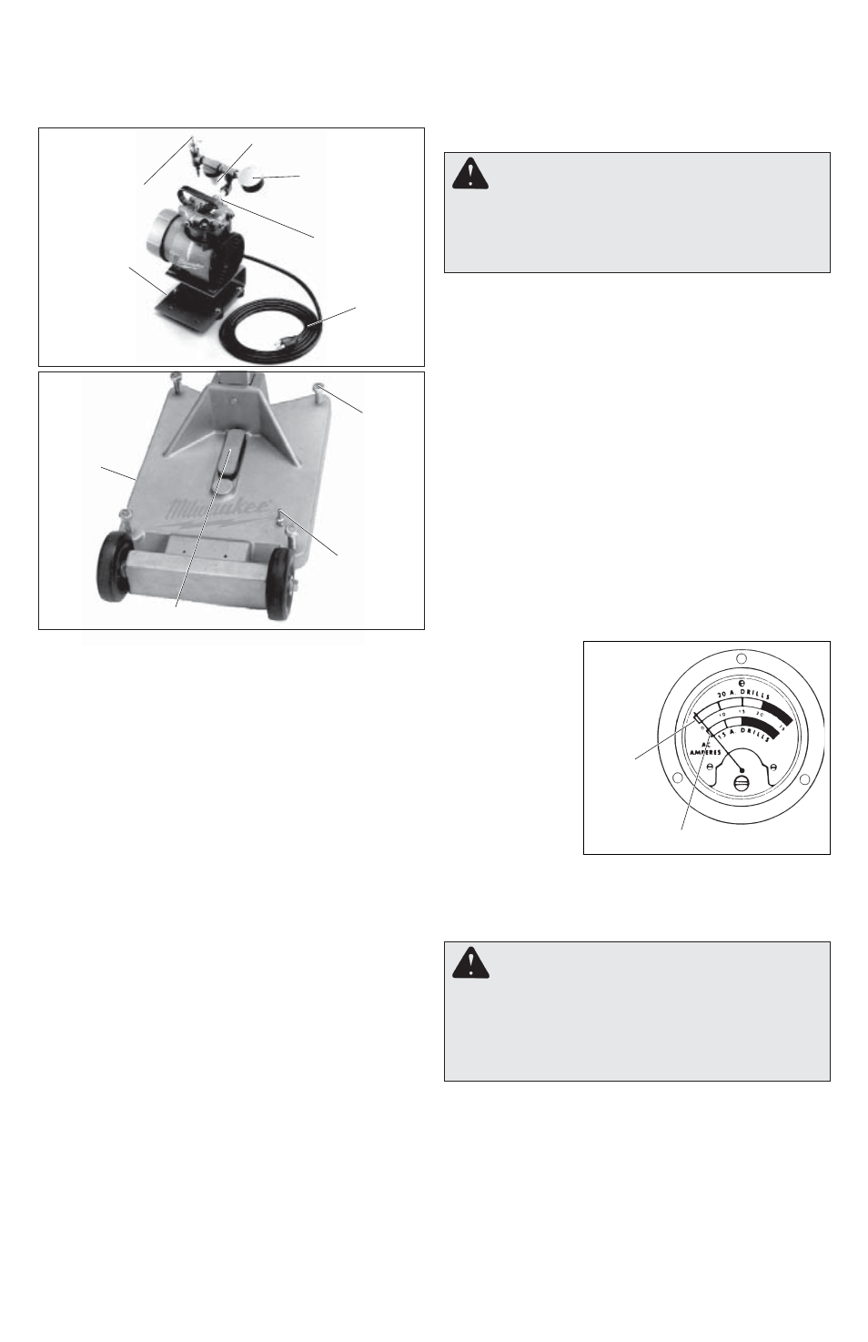
Reading the Meter Box
The ammeter is
the dial indicator
on the meter box,
which is standard
equipment with
the Vac-U-Rig
®
and can be pur-
c h a s e d s e p a -
rately for other
Dymorigs. The
a m m e t e r p r o -
vides pressure
feedback during
coring, allowing you to help prevent motor overload
and premature bit wear. The green area on the
ammeter is the operating range and the red area
indicates that you are applying too much pressure.
Using the Optional Telescoping Assembly
1. Secure the rig using either an expansion-type
anchor or a vacuum system (see "Securing the
Equipment to the Work Surface").
2. Place the top fl ange of the extension against
a ceiling or wall and place the other end
on the jack screw at the top of the Dymorig
column.
The assembly is adjustable up to 14 feet. Turn
the jack screw to tighten the assembly and to
make small adjustments.
20 Amp
Operating
Range
15 Amp Operating Range
Fig. 16
WARNING
To reduce the risk of injury,
always use Dymodrills in conjunction with
meter boxes. Meter Boxes provide a switch
to turn the Dymodrill motor OFF and ON and
an optimum operation range to help prevent
motor overload.
Shear Pin and Clutch
Dymodrill Nos. 4079, 4090, and 4094 contain a
shear pin to protect the gear and motor against
overload. This pin drives the spindle sleeve. If the
bit binds, the pin will shear to prevent gear and
motor damage. Extra shear pins are supplied with
each Dymodrill and can be replaced (see "Acces-
sories" for part numbers). It is important to check the
condition of the spindle before using the tool each