Assembly warning, Specifications – Milwaukee Tool 4125 User Manual
Page 5
5
ASSEMBLY
WARNING
To reduce the risk of injury,
always unplug tool before changing or re-
moving accessories. Only use accessories
specifi cally recommended for this tool. Others
may be hazardous.
SPECIFICATIONS
Cat.
No.
Amps Volts
Motor
Protection
Speed
Suggested Diameters in
Medium Aggregate
4004
20
120
Clutch
Low - 300 High - 600
Low - 7" - 14" High - 4" - 7"
4005
20
120
Clutch
Low - 600 High - 1200
Low - 4" - 7" High - 3/4" - 4"
4079
20
120
Shear Pin
Low - 300 High - 600
Low - 7" - 14" High - 4" - 7"
4090
15
120
Shear Pin
Low - 375 High - 750
Low - 5" - 8" High - 2-1/2" - 5"
4094
20
120
Shear Pin
Low - 450 High - 900
Low - 6" - 10" High - 2" - 6"
4096
20
120
Clutch
Low - 450 High - 900
Low - 6" - 10" High - 2" - 6"
4097-20
15
120
Clutch
Low - 500 High - 1000
Low - 3" - 5" High - 1-1/4" - 3"
Assembling Dymorigs & Vac-U-Rig® Stands
For Cat. No. 4125 & 4130 only
1. Set the base on the ground. Loosen the hex bolt
and nut (wrench not supplied). Raise the column
upright.
2. To core vertically or horizontally, insert the
large column bolt (provided in separate acces-
sory bag) through the bottom of column and into
the base. Tighten hex bolt and nut (wrench not
supplied).
To angle core, tilt the column to the desired
angle and tighten the hex bolt and nut. Save
the column bolt for future use when vertical or
horizontal coring.
3. Tighten the two (2) black socket set screws
located on the base with the supplied wrench.
4. Screw the four (4) handle spokes (provided in
separate accessory bag) into the hub on the
cradle assembly.
For Cat. No. 4115 & 4120 only
1. Set the base on the ground.
2. Remove two (2) bolts and two (2) lockwashers
from accessory bag.
3. Place the column in the slot of the base.
4. Insert two (2) bolts and two (2) lockwashers and
tighten securely.
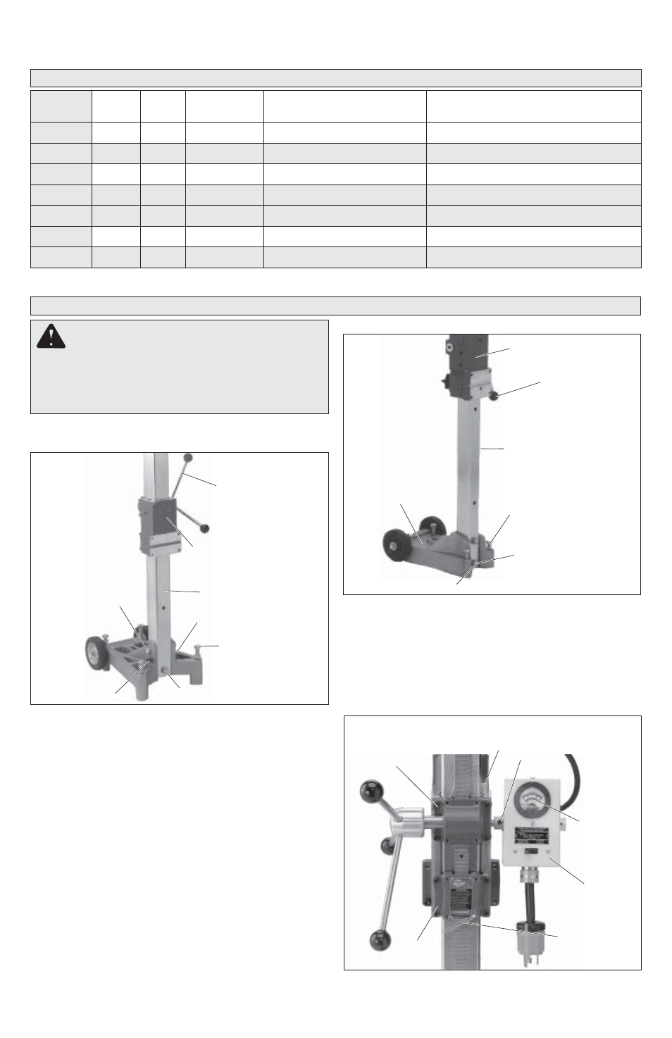
Fig. 1
Handle
spoke
Cradle
assembly
Column
Base
Leveling
screws (4)
Column bolts
Socket set
screws (2)
Hex bolt
Moving the Handle to the Other Side
For Cat. Nos. 4125 & 4130 only
Fig. 2
Cradle assembly
Handle
spoke
Column
Base
Leveling
screws (4)
Column
bolts (2)
Lock washers
Socket
screws (4)
Fig. 3
Bubble level
Socket
screw
Ammeter
gauge
Meter
box
Cradle
lock
Cradle