2 recommended configuration – Maxim Integrated 78M6610+PSU Hardware Design Guidelines User Manual
Page 2
78M6610+PSU Hardware Design Guidelines
AN_6610_107
2
Rev 0
2 Recommended Configuration
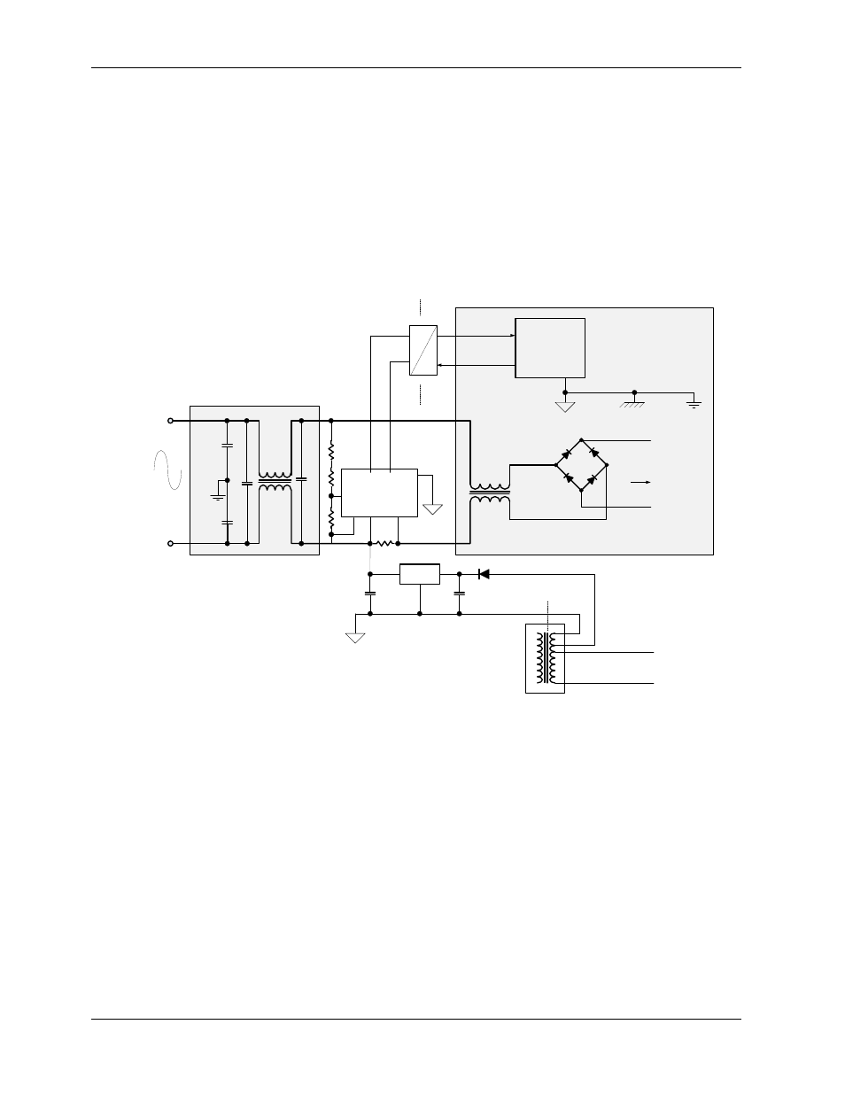
Resistive current shunts and voltage dividers are commonly used to meet system limitations on size and
cost. When using a shunt current sensor, the measurement IC and its power domain are directly
connected to AC mains. In this case, the 78M6610+PSU measurement device is typically powered
through an auxiliary winding of the SMPS transformer (generally the stand-by channel). To protect the
auxiliary winding from surge events and avoid switching noise from being conducted onto AC mains, the
resistive sensors are located behind the EMI filter.
The system communicates with the 78M6610+PSU across data isolators (i.e. opto-couplers or digital
isolators) as the host controller is located on the secondary side and often referenced to earth ground.
The UART interface is suggested for lowest cost of data isolation.
78M6610+PSU
LDO
ISOLATED
GROUND
ISOLATED
GROUND
SMPS
TRASFORMER
AC
INLET
To PFC
TX
RX
HOST
PROCESSOR
CHASSIS
EARTH
GROUND
SYSTEM GROUND
GALVANIC ISOLATION
OPTO-
COUPLERS
GALVANIC
ISOLATION
EARTH
GROUND
LINE
NEUTRAL
Figure 1: Typical Implementation of 78M6610+PSU