4 connecting 5 v devices, 5 driving external loads, 6 serial interfaces – Maxim Integrated 78M6610+PSU Hardware Design Guidelines User Manual
Page 13
AN_6610_107
78M6610+PSU Hardware Design Guidelines
Rev. 0
13
4.4 Connecting 5 V Devices
All digital input pins (DIO pins) of the 78M6610+PSU are 5 V tolerant allowing connection to external 5 V
devices. I/O pins configured as inputs do not require current-limiting resistors when they are connected to
external 5 V devices.
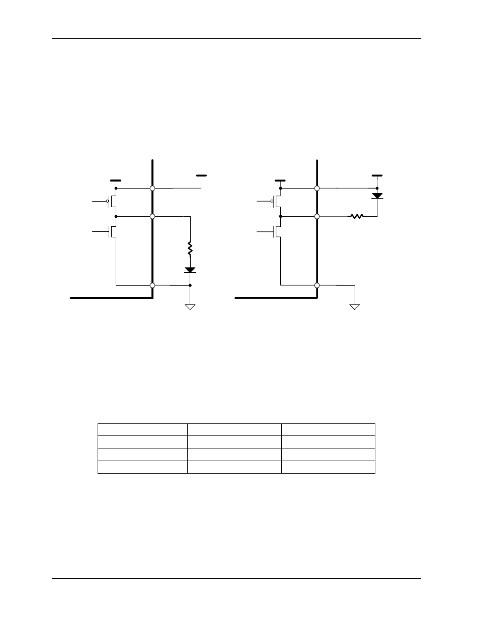
4.5 Driving External Loads
Even though the current output for the 78M6610+ PSU are similar driving high or low, if current is sourced
by the &8M6610+PSU, the digital power supply current to V3P3D will be increased by that amount. See
Figure 9 for our preferred connection. Sourcing current when the output is high is allowed but will add to
the apparent V3P3D current for the part.
GNDD
V
3P3
GNDD
NOT RECOMMENDED
RECOMMENDED
V
3P3
DIO
V
3P3
V
3P3
DIO
LED
LED
78M6610+PSU
78M6610+PSU
Figure 9: Connecting an External Load to a Digital Output
4.6 Serial Interfaces
The 78M6610+PSU has on-chip UART, I
2
C, and SPI serial interfaces selectable through the configuration
of the pins IFCONFIG and SSB/DIR/SCL according to the following table. The status of these pins is
sampled at power-on or reset. Both the SSB/DIR/SCL and IFCONFIG pins contain internal 50-200K pull-
up resistors so unconnected pins default to 1.
Selected Interface
SSB/DIR/SCL
IFCONFIG
SPI
X (don’t care)
0
UART
0
1
I
2
C
1
1
For I
2
C operation, it is assumed that the I
2
C master does not activate the clock (SCL) until after the
78M6610+PSU has completed its startup.
For UART operation, the RS-485 driver enable pin will be monetarily low until the 73M6610+PSU
completes its startup.