2 clock circuitry – Maxim Integrated 78M6610+PSU Hardware Design Guidelines User Manual
Page 11
AN_6610_107
78M6610+PSU Hardware Design Guidelines
Rev. 0
11
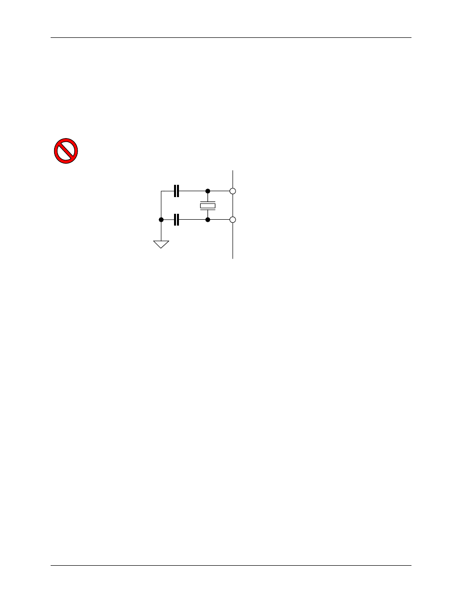
4.2 Clock Circuitry
The 78M6610+PSU can utilize an external 20.000 MHz crystal for optimum performance. The circuitry
includes two ceramic capacitors. The selected crystal must have a specified 18 pF load capacitance.
The oscillator is specifically designed for these types of crystals which have high impedance and limited
power handling capability. The oscillator design minimizes power dissipation.
Minimize the printed circuit board capacitance for XIN to XOUT. Encase XIN and XOUT with a ground
shield to minimize external noise interference of the low power oscillator.
The oscillator is self-biasing. Do not connect an external resistor across the crystal.
Figure 7: Crystal Connections
An external clock signal can be utilized instead of the crystal. In this case the external clock should be
connected to the XOUT pin while the XIN pin should be connected to GNDD.
If the external crystal is not utilized (not mounted), the internal oscillator is selected automatically. In this
case the XOUT pin should be connected to GNDD and the XIN pin left unconnected. Refer to the
78M6610+PSU Data Sheet for parametric data relating to internal oscillator operation.
XIN
XOUT
18 pF
18 pF
20 MHz
78M6610+PSU