Maxim Integrated MAX-IDE MAXQ Microcontrollers User Manual
Page 8
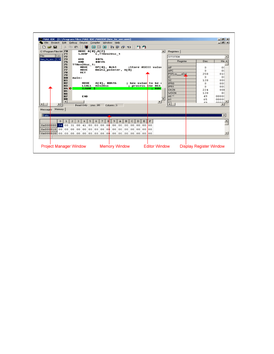
Figure 5. The Debug Windows with the breakpoint are indicated by the green arrow and line.
Step 11: Open up the registers window by clicking on
Window→Show→Registers from the Window
menu. Select SYSTEM from the Registers drop-down box to display the MAXQ core registers' contents.
Observe that relevant registers are updated as you step through the execution. Try the commands step
into, step over, step out, and run to cursor to become familiar with the MAX-IDE. Similarly, if your
program is writing to the data memory and you want to watch the data values, go to
Window→Show→Memory, tab to "data" memory, and scroll down to the memory location to observe
the values.
The above program converts the hex value supplied in the A [0] register to its equivalent ASCII value,
and stores the ASCII values in the data memory addresses 0x00 and 0x02.
Execute the application for different values in the A [0], and observe their equivalent ASCII values in
data memory addresses 0x00 and 0x02.
Refer back to Figure 4. A [0] is set to 0x41 HEX in the registers window; data memory location 0x00 and
0x02 are updated with 0x34 and 0x31 respectively, which are the ASCII equivalent of 0x41 hex.
Step 12: Open the Statistics window (
Window→Show→Statistics). This action shows you the machine
cycles and execution time (Figure 5).
Page 8 of 11