Warning, I. general operation of heat exchangers, J. general operating principle – Leslie Controls NYC Heat Exchanger User Manual
Page 11
Page 11 of 25
I.
GENERAL OPERATION OF
HEAT EXCHANGERS
Heat exchangers are designed to transfer heat between
steam and water at various temperatures, fluid flows, and
pressures.
CONSTRUCTION FEATURES
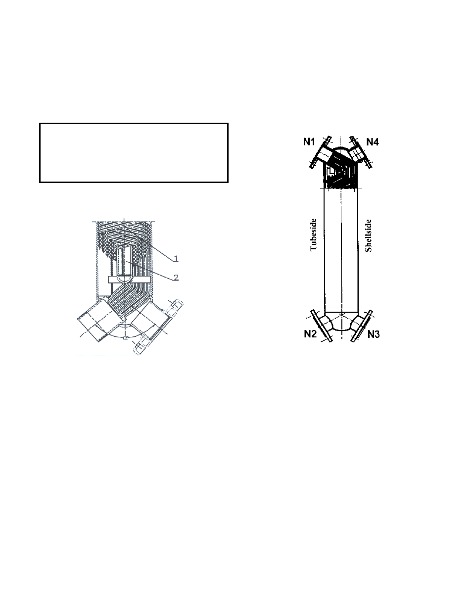
Figure 7 - Cross Section
Heat exchangers are designed and fabricated as a single
unit with non-removable parts. Cylindrical shell encloses
a tube bundle which consists of circular layers of helically,
corrugated tubes. Each layer flows in opposite direction to
layers surrounding it in a criss-cross manner. Tube bundle
has
perforated
bottom,
which
are
welded
near
connections. Both ends of cylindrical shell are enclosed
within hemispherical heads.
Each heat exchanger has a total of four (4) symmetrically
located connections, two on each hemispherical head. One
pair of opposing connections is connected to tube side
while other pair is connected to shell side.
J. GENERAL OPERATING
PRINCIPLE
A heat exchanger is a device in which heat is transferred
from one flowing fluid to another. Shell and Tube heat
exchangers are most common type of heat exchangers.
These heat exchangers are counter flow units, which from
a thermodynamic point of view extract more heat from a
given fluid stream than order common types of heat
exchangers.
Heating medium flows through tubes. Thermal energy is
transferred through tube walls. Total heat load is
dependent on flow parameters of fluid.
Figure 8 – Flow Distribution in Heat Exchangers
WARNING!
FLUSH HEAT EXCHANGERS
WITH FRESH CLEAN WATER EVERY SIX
MONTHS. An inspection and maintenance log must
be maintained.