LAARS Pennant PNCV (Sizes 200, 300, 400) - Install and Operating Manual User Manual
Page 9
LAARS Heating Systems
Page 8
Pennant 200, 300, 400
Page 9
the National Fuel Gas Code, ANSI Z223.1. In Canada,
the applicable sections of the Natural Gas and Propane
Installation Code (CSA B149.1) must be followed. In
all cases any and all applicable local installation codes
must also be followed.
A Pennant appliance may receive combustion
air from the space in which it is installed, or it can be
ducted directly to the unit from the outside. Proper
ventilation air must be provided in either case.
2.1.1 Combustion Air From Room
In the United States, the most common
requirements specify that the space shall communicate
with the outdoors in accordance with method 1 or 2,
which follow. Where ducts are used, they shall be of
the same cross-sectional area as the free area of the
openings to which they connect.
Method 1
: Two permanent openings, one
commencing within 12 inches (30 cm) of the top
and one commencing within 12 inches (30 cm) of
the bottom, of the enclosure shall be provided. The
openings shall communicate directly, or by ducts,
with the outdoors or spaces that freely communicate
with the outdoors. When directly communicating
with the outdoors, or when communicating to the
outdoors through vertical ducts, each opening shall
have a minimum free area of 1 square inch per 4000
Btu/hr (5.5 square cm/kW) of total input rating of all
equipment in the enclosure. When communicating to
the outdoors through horizontal ducts, each opening
shall have a minimum free area of not less than
1 square inch per 2000 Btu/hr (11 square cm/kW) of
total input rating of all equipment in the enclosure.
Table 3 shows data for this sizing method, for each
Pennant model.
Method 2
: One permanent opening, commencing
within 12 inches (30 cm) of the top of the enclosure,
shall be permitted. The opening shall directly
communicate with the outdoors or shall communicate
through a vertical or horizontal duct to the outdoors
or spaces that directly communicate with the outdoors
and shall have a minimum free area of 1 square inch
per 3000 Btu/hr (7 square cm/kW) of the total input
rating of all equipment located in the enclosure. This
opening must not be less than the sum of the areas of
all vent connectors in the confined space.
Other methods of introducing combustion and
ventilation air are acceptable, providing they conform
to the requirements in the applicable codes listed
above.
In Canada, consult local building and safety
codes or, in absence of such requirements, follow
CSA B149.1, the Natural Gas and Propane Installation
Code.
Boiler
Model
Each Opening*
Square inches
Square cm
200
50
323
300
75
484
400
100
645
*Net Free Area in Square Inches / Square cm
Area indicated is for one of two openings; one at floor level
and one at the ceiling, so the total net free area could be
double the figures indicated.
This chart is for use when communicating directly with the
outdoors. For special conditions and alternate methods, refer
to the latest edition of ANSI Z223.1.
Note: Check with louver manufacturers for net free area of
louvers. Correct for screen resistance to the net free area
if a screen is installed. Check all local codes applicable to
combustion air.
Table 3. Combustion Air Openings.
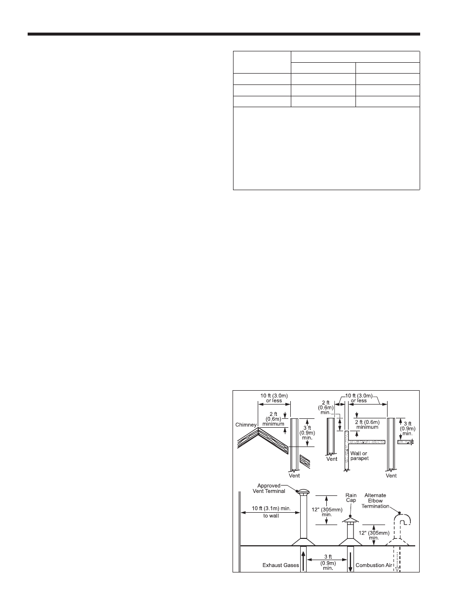
2.1.2 Intake Combustion Air
The combustion air can be taken through the
wall, or through the roof. When taken from the wall, it
must be taken from out-of-doors by means of the Laars
horizontal wall terminal (see Table 1). When taken
from the roof, a field-supplied rain cap or an elbow
arrangement must be used to prevent entry of rain
water (see Figure 2).
Use single-wall galvanized pipe, per Table
4, for the combustion air intake (see Table 1 for
appropriate size). Route the intake to the heater as
directly as possible. Seal all joints with tape. Provide
adequate hangers. The unit must not support the
weight of the combustion air intake pipe. Maximum
linear pipe length allowed is 50 feet (15.2m). Three
elbows have been calculated into the 50-foot (15.2m)
linear run. Subtract 10 allowable linear feet (3.0m) for
every additional elbow used (see Table 1). When fewer
Figure 2. Combustion Air and Vent Through Roof.