4a.2 cold water make-up — boiler, 4a.3 water flow requirements — boiler, Laars heating systems – LAARS Pennant PNCV (Sizes 200, 300, 400) - Install and Operating Manual User Manual
Page 19
LAARS Heating Systems
Page 18
Pennant 200, 300, 400
Page 19
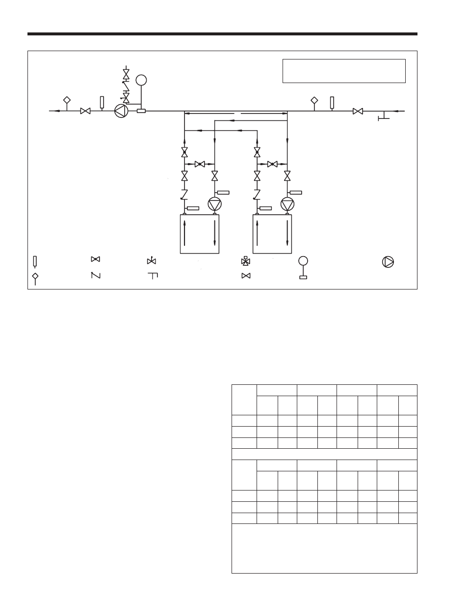
Figure 8. Hydronic Piping — Primary-Secondary, Reverse-Return, Low Temperature.
CAUTION: THIS DRAWING SHOWS SUGGESTED
PIPING CONFIGURATION AND VALVING, CHECK
WITH LOCAL CODES AND ORDINANCES FOR
ADDITIONAL REQUIREMENTS.
PRIMARY/SECONDARY MANDATORY FOR ALL
VARIABLE FLOW SYSTEMS
INSTALL AIR VENTS AT HIGH POINTS IN SYSTEM
PIPING & SIZING OF EXPANSION TANK
PER TANK MANUFACTURER'S INSTRUCTIONS
DIMENSION "C" (COMMON PIPING) TO BE FOUR
PIPE DIAMETERS, MAX. (NO ELBOWS OR VALVES)
BOILER CIRCUIT PIPING MUST BE EQUAL
TO BOILER WATER CONNECTION SIZE
BOILER CIRC. PUMP SIZED FOR FLOW THROUGH BOILER
DOTTED DEVICES INDICATE ALTERNATE LOCATIONS
PUT BOILER CONTROL SENSOR IN THE SYSTEM
SUPPLY WHEN USING THIS PIPING STYLE.
MINIMUM BOILER INLET WATER TEMPERATURE
MUST BE AT LEAST 120°F.
C
SYSTEM PUMP
MAKE-UP
COLD WATER
SUPPLY
SYSTEM
PUMP LOCATION FOR
PUMP-MOUNTED UNITS
RETURN
SYSTEM
T1
T1
A
B
A
B
ADJUSTMENT PROCEDURE TO MAINTAIN
120°F INLET TEMP:
1. Turn on boiler and open valves A & B.
2. After steady-state operation, if T1 is less than
120°F, slowly close valve B until T1 climbs to
120°F.
3. If T1 is greater than 120°F, slowly close valve
A until T1 drops to 120°F.
4. Check after system operating temperature has
stabilized. Make final adjustments.
CHECK VALVE
TEMPERATURE
SENSOR
VALVE
PURGE VALVE
THERMOMETER
GLOBE VALVE
EXPANSION TANK
WITH AIR SCOOP AND
AUTO AIR VENT
PUMP
PRESSURE REDUCING VALVE
W/ FAST FILL BYPASS
3-WAY VALVE
Model
(Size)
20°F
25°F
30°F
35°F
flow
gpm
H/L
feet
flow
gpm
H/L
feet
flow
gpm
H/L
feet
flow
gpm
H/L
feet
200
17
1.6
14
1.0
11
0.7
10
0.5
300
26
3.5
20
2.3
17
1.6
15
1.2
400
34
6.3
27
4.0
23
2.8
19
2.1
Metric Equivalent
Model
(Size)
11°C
14°C
17°C
19°C
flow
lpm
H/L
m
flow
lpm
H/L
m
flow
lpm
H/L
m
flow
lpm
H/L
m
200
64
0.5
51
0.3
43
0.2
37
0.2
300
97
1.1
77
0.7
64
0.5
55
0.4
400
129
1.9
103
1.2
86
0.9
74
0.6
Notes: gpm = gallons per minute, lpm = liters per minute,
H/L = head loss, ft = head loss in feet,
m = head loss in meters.
Maximum temperature rise is 35°F (19°C), as shown.
Head loss is for boiler’s heat exchanger only.
N/R = not recommended.
Table 8. Water Flow Requirements - PNCH.
4A.2 Cold Water Make-Up — Boiler
1. Connect the cold water supply to the inlet
connection of an automatic fill valve.
2. Install a suitable back flow preventer between the
automatic fill valve and the cold water supply.
3. Install shut off valves where required.
NOTE: The boiler, when used in connection with a
refrigeration system, must be installed so the chilled
medium is piped in parallel with the boiler with
appropriate valves to prevent the chilled medium
from entering the boiler.
The boiler piping system of a hot water heating
boiler connected to heating coils located in air
handling appliances where they may be exposed to
refrigerated air circulation must be equipped with flow
control valves or other automatic means to prevent
gravity circulation of the boiler water during the
cooling cycle.
A boiler installed above radiation level, or as
required by the authority having jurisdiction, must be
provided with a low water cutoff device either as a part
of the boiler or at the time of boiler installation.
4A.3 Water Flow Requirements — Boiler
A hydronic heating (closed loop) application
recirculates the same fluid in the piping system. As a
result, no new minerals or oxygen are introduced into
the system. To ensure a proper operating temperature
leading to long boiler life, a flow rate has been
established based on the fluid temperature rise for this
specific size boiler.
Pump-mounted boilers can be ordered for use in
primary secondary piping systems. The pumps used
are sized for the head loss through the heater, plus 30
feet (9.1 m) of full-sized piping (same size as boiler
outlet) and a normal number of fittings.