LAARS EDN Series - Installation, Operation and Maintenance Instructions User Manual
Page 23
Endurance
Page 23
The EBP modulating combination boiler will
start from any of three input signals: (a)T-T closure
for space heating. (b)A demand for domestic hot
water, signaled by water flow activation of the water
flow switch. (c)A call for heat from the minimum
tank temperature sensor at 158°F (tank charge mode).
In tank charge mode the red LED located below the
green LED on the PCB will be lit. In modes (b) and
(c) which are priority modes, the internal anti-
condensing valve will be closed. On a T-T call for
heat the valve will remain closed until the priority
modes are satisfied.
[Service note: as with the thermostatic union in
the EDP/EDN models, the anti-condensing valve
prevents condensation on the combustion chamber coil
and must be in the closed position when the coil inlet
(F6) indicates a temperature below 130°F].
8.2 Trouble Shooting - Fault Codes
The Endurance boiler is controlled by a Pactrol
integrated boiler control (PCB) which provides eight
fault codes with eight memories. To obtain fault
messages press-in on the message center fault button
until the first fault code (FLI) is displayed.
If a thermistor error occurs, it will appear on the
LED upon power-up. The memory does not need to
be accessed. Memory fault codes are for error
history only. All thermistor faults will show as “F”
codes on the LED, and will never cause the LED to
read “LO”. (Note that the unit is shipped with error
codes already in memory, and an error code that is
shown in memory upon start-up of a new unit is from
manufacturing testing.)
The last recorded fault will appear e.g. F-4 (flow
thermister faulty - open or shorted). The control will
then sequence through all eight memories, indicating
alternately the fault number and the fault code (FL1,
F-?; FL2, F=?; …, FL8, F=?). The fault number in
fault code FL1 is the most recent fault.
8.2.1 Fault Code Identification
The following eight fault codes may be observed:
F-
Error corrected, control in auto reset time
period (10 seconds)
F-0 No fault has occurred
F-1 Error occurred reading fault logic of main
control
F-2 Over heat thermostat has operated
(open circuit)
F-3 Fan fault
F-4 Flow temperature sensor faulty
(open or short circuited)
F-5 Tank temperature sensor faulty
(open or short circuited) (Combi unit only)
F-6 Return temperature sensor faulty
(open or short circuited)
8.2.2 Fault Correction (see also Fault
Trees in this Section)
F-1 Switch off boiler and restart. If F-1 repeats,
replace PCB
F-2 The overheat thermostat (safety limit)
opens at 230°F. Observe boiler operation if
the boiler shuts off before the
indicates
225°F (107°C) replace safety limit. If the
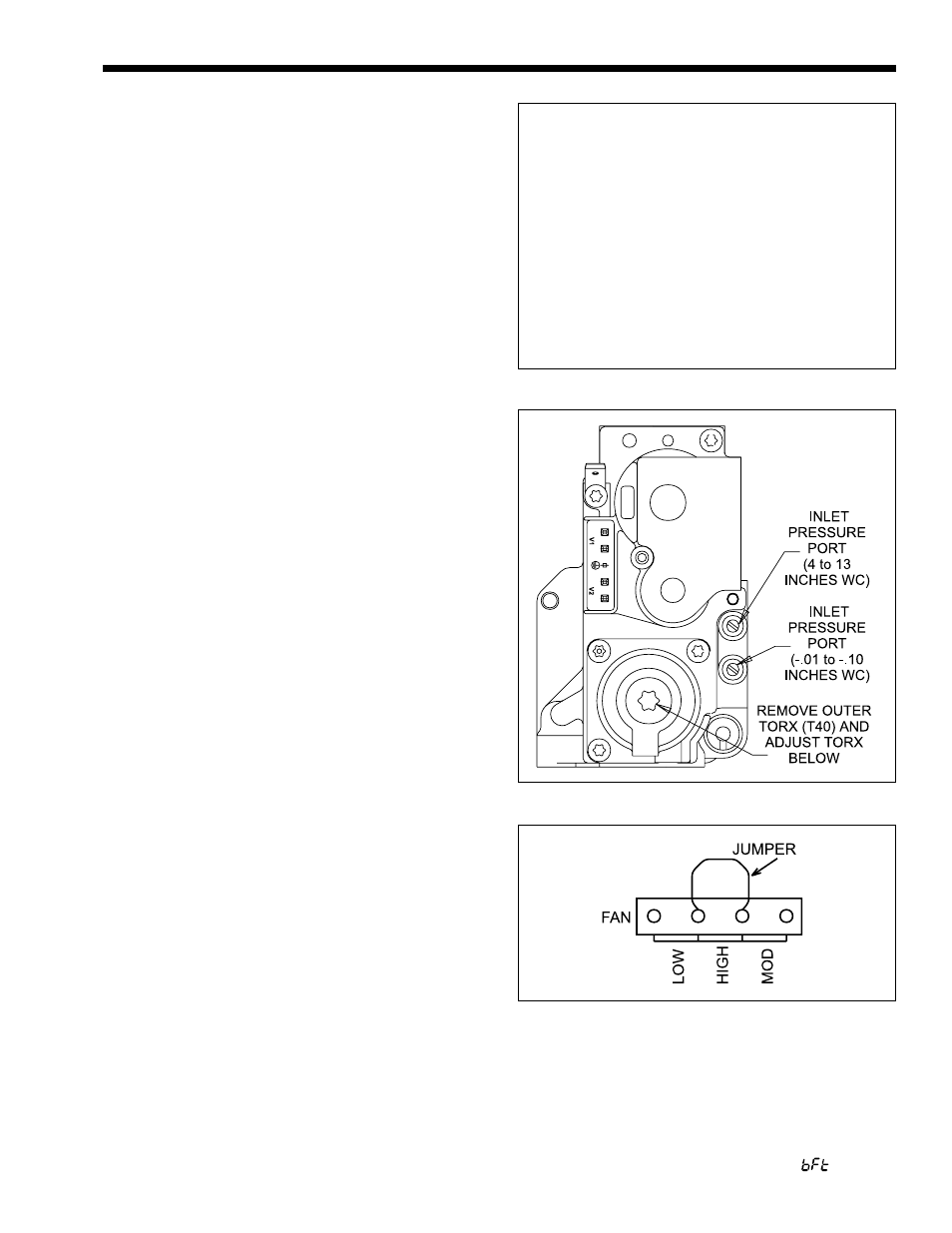
Figure 29.
Table 4. EBP/EDP 175.
MEASUREMENTS AT HIGH FIRE
NATURAL GAS
% CO
2
9.0 - 9.6
MAX INPUT
175,270
BTU/H
OFFSET
(-0.01 to -.10)
IN W.C.
LP GAS
% CO
2
9.7 - 10.1
MAX INPUT
175,270
BTU/H
OFFSET
(-0.01 to -.10)
IN W.C.
Figure 30. Jumper Wiring for Test and Calibration.