LAARS EDN Series - Installation, Operation and Maintenance Instructions User Manual
Page 21
Endurance
Page 21
7.6 Transformer
The control transformer accepts 120 VAC line
voltage and provides 80 VA of 24 VAC control
voltage for the boiler control ONLY. It is NOT
capable of supplying control voltage for external
devices such as zone valves, which MUST have their
own separate power supply.
Should the transformer require replacing, shut off
the 120 volt power. Unplug the transformer wires from
the PCB, unscrew the two fixing screws and remove
the transformer.
Fit the replacement transformer in reverse order.
7.7 Blower
The combustion air blower is a high pressure
centrifugal blower. It is powered by a 24VDC motor
which is controlled by the PCB. Its speed will be
varied according to the temperature of the boiler flow.
If a blower change is required, turn off the 120
volt power and unplug the wires from the blower
motor. Remove the four nuts from the blower
discharge flange and the four screws that secure the
gas manifold to the gas valve. Remove the complete
assembly. Unscrew the combustion air inlet assembly
and register plate from the fan.
Fit the replacement fan in reverse order, ensuring
that all joints are made correctly and sealed.
After replacement the combustion should be
checked for correct air fuel ratio (see Check, Test and
Start-Up section).
7.8 Transfer Tank (EBP)
The transfer tank contains approximately 20
gallons of boiler water. It functions as an energy
storage vessel to reduce boiler cycling on small output
heating zones and to provide additional heat for
domestic hot water through the domestic hot water
(DHW) plate heat exchanger.
If a tank change is necessary, access to the tank is
possible by removing the jacket’s lower front panel.
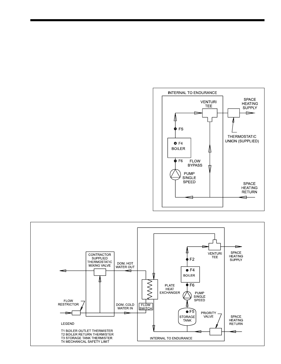
Figure 28. EBP Flow Schematic.
Figure 27. EDP/EDN Flow Schematic.