7 locating unit for proper vent height, 8 locating unit with respect to ventilation, 9 installing vent piping terminal – LAARS 9600 CB - Installation, Operation and Maintenance Instructions User Manual
Page 7: 10 connecting gas to the cb boiler
9600 CB
Page 7
The center line of the hole should be at least 16"
(24cm) above grade outdoors. The inlet opening of
the intake fitting must be 6" (15cm) below the center
line for the exhaust vent, and 18" (27cm) away from
the exhaust vent outlet. The intake fitting should never
be located above the exhaust vent terminal. Refer to
Figures 3, 4, and 5 for acceptable configurations.
1.7 Locating Unit for Proper Vent Height
The vent locations you select must permit direct
pipe runs to the terminal from the boiler. Since the
CB boiler is designed to drain any water that collects
in the vent, it is important that you do not build any
traps or low points into the vent where water could
collect and restrict the vent. It is recommended that 1/
4 inch per foot of vent be built into the vent system to
direct any water in the vent back toward the boiler.
Note that standard DWV elbows have a built in
allowance for the required 1/4 per foot pitch.
1.8 Locating Unit with Respect to
Ventilation
While the CB boiler requires no indoor air for
combustion, adequate airflow around the unit must be
provided for proper cooling of electrical components.
Locating unit with respect to the return/supply
header. For the best results the CB boiler should be
located within 10 feet of the supply and return
headers.
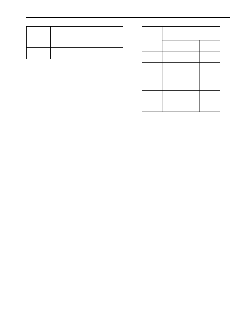
If the unit must be installed with longer piping
runs, then the larger diameter tubing must be used.
Table 1 is used to calculate the necessary pipe size
for your installation.
1.9 Installing Vent Piping Terminal
The boiler is provided with intake and exhaust
terminals for use with 3" diameter plastic pipe.
The installer is responsible for obtaining the
vent pipe and fittings. The maximum combined length
of the intake and exhaust pipe and maximum number
of elbows are determined by using the guidelines on
Page 4.
The following steps are recommended for vent
installation:
a.
Obtain the necessary 3" or 4" diameter plastic
piping and fittings as determined beforehand.
b.
Position unit at previously selected location.
c.
Unpack vent terminals and vent terminal backing
plates located beneath lower front panel.
d.
Cut holes in outside wall for vent terminals in
previously selected locations.
e.
Mount the vent terminals backing plates.
f.
Fit all of the vent pipes together without
cementing. Make sure that there are no water
traps and that any pitch is inclined back towards
the boiler.
g.
Make sure that the flexible vent connections at
the unit fit properly.
h.
Begin cementing the intake and exhaust pipes, start
at the vent terminals and work back towards the
appliance. Note that the intake terminal is a 90
degree elbow fitting that is designed to face down.
i.
Support both horizontal vent pipes with pipe
hangers every 5'. Weight of venting must not be
supported by unit connectors.
j.
Tighten the flexible couplings to connect the
boiler to the vent.
Heating System Piping. Note: This unit must be
installed in a closed pressure system with a minimum
of 10 psi static pressure.
1.10 Connecting Gas to the CB Boiler
a.
The boiler requires gas at an inlet gas pressure
of at least 4" WC and no greater than 13" WC.
Check with your local gas utility or supplier for
availability of these delivery pressures.
b.
Referring to Table 2, size supply piping to keep
flow capacity to the unit above 250 cubic feet
per hour (CFH) per unit installed.
c.
Run gas supply line in accordance with all
applicable codes.
d.
Locate and install manual shutoff valves in
accordance with state and local requirements.
e.
Install drip leg and ground joint union (Figure 4).
f.
All threaded joints should be coated with piping
Table 3. Gas Supply Piping.
Table 2. Water Pipe and Tube Sizing.
Copper tube
Maximum
Amount
Amount
or pipe
allowable
deducted for
deducted for
size
tubing length
each 90°
each 45°
elbow
elbow
1¼"
40'
2'
1½'
1½"
120'
2'
1½'
2"
270'
2'
1½'
Length
Capacity of Pipe
of
in MBTU/HR
Pipe
(.6 Specific Gravity)
¾"
1"
1¼"
10'
278
520
1,050
20'
190
350
730
30'
152
285
590
40'
130
245
500
50'
115
215
440
75'
93
175
360
100'
79
150
305
150'
64
120
250
Additional
length to be
added for
1.7'
2.2'
2.7'
each tee
or bend