LAARS 9600 CB - Installation, Operation and Maintenance Instructions User Manual
Page 10
Page 10
LAARS Heating Systems
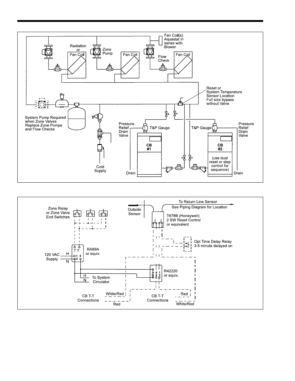
Figure 11. Piping diagram for modular units and/or hydro air systems.
Figure 12. Wiring diagram.
1.12 Return Connections
a.
Install a strainer between CB and system.
b.
Connect the 1¼" return connection on the unit to
the return side of the system circulating loop.
c.
Install a check valve (multiple units only), a
shutoff valve and a drain valve near the unit in the
return line.
d.
Install a properly sized circulator in the system
loop.
1.13 Cold Water Make-Up
a.
Connect the cold water supply to the inlet
connection of an automatic fill valve.
b.
Install a suitable back flow preventer between the
This manual is related to the following products: