3 unpacking, 4 locating the cb boiler – LAARS 9600 CB - Installation, Operation and Maintenance Instructions User Manual
Page 4
Page 4
LAARS Heating Systems
1.3 Unpacking
The CB boiler is shipped in a single carton with
the following standard components on top of the unit.
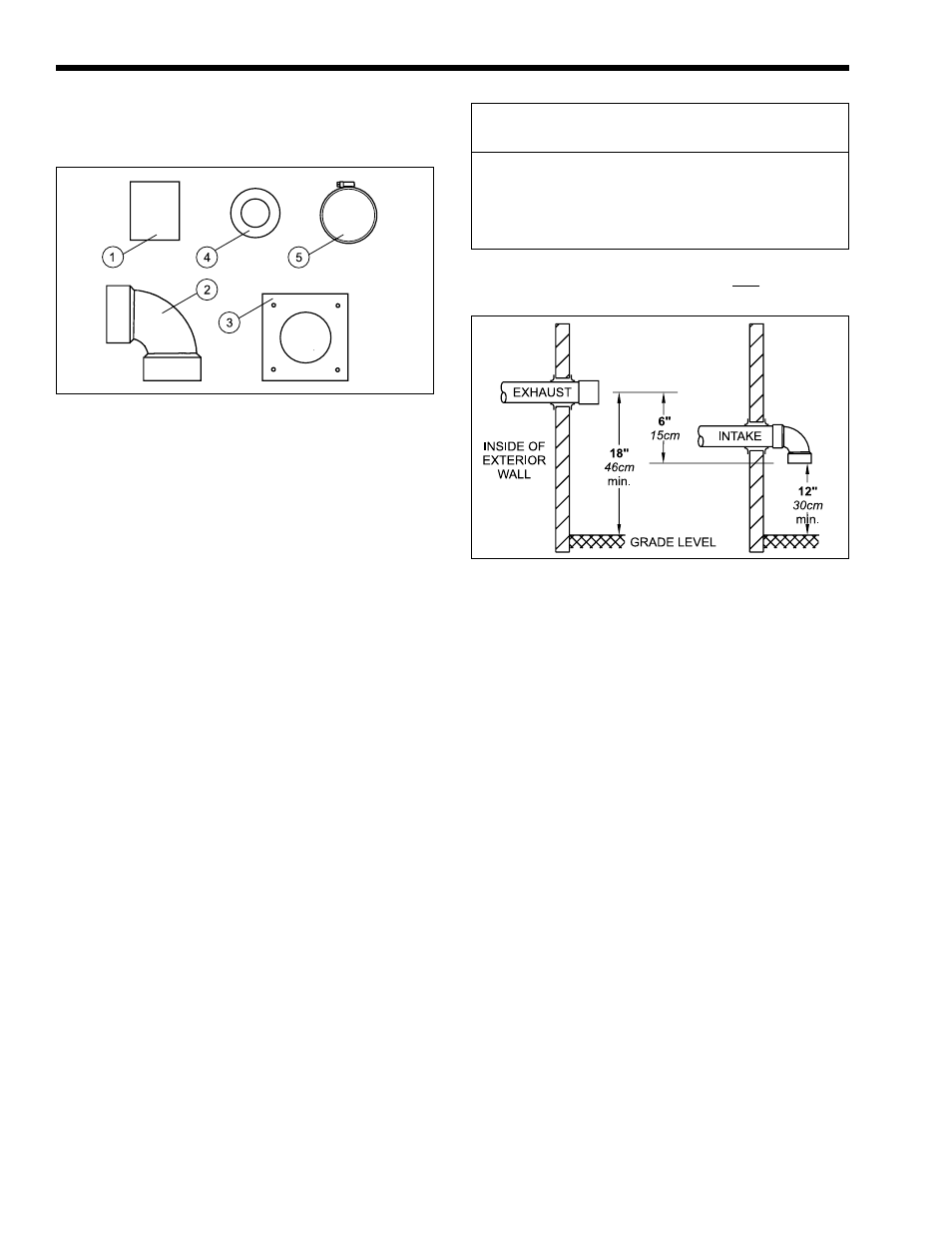
Figure 2. Contents of shipping package.
1. Exhaust terminal
4. Hubless coupling reducer
2. Intake terminal
5. Hubless couplings (2)
3. Backing plates (4)
a.
Remove all packing and tie-down materials.
b.
Check contents of the carton against items
shown above.
1.4 Locating the CB Boiler
The appliance should be located in an area
where leakage of any connections will not result in
damage to the area adjacent to the appliance or to
lower floors of the structure.
When such a location is not available, it is
recommended that a suitable drain pan, adequately
drained, be installed under the appliance.
The unit is design certified by CSA for
installation on combustion flooring; in basements; in
closets, utility rooms or alcoves. It must not be
installed on carpeting.
The location for the unit should be chosen with
regard to the vent pipe lengths, external plumbing,
ventilation of operating components and accessibility
for service and cleaning.
The unit shall be installed such that the gas
ignition system components are protected from water
(dripping, spraying, rain, etc.) during operation and
service (circulator replacement, control replacement,
etc.).
If there is potential for snow accumulation in
your area, both vent terminals should be installed at an
appropriate level above grade.
The following dimensions and requirements
should be met when choosing the locations for the
unit:
a.
Minimum clearance from combustible materials
to meet CSA requirements.
b.
Recommended clearance for accessibility and
venting.
Clearance from
Service
Combustible Material
Access Clearance
Surface
U.S. / Canada
U.S.
Canada
Left Side
1"
2.5cm
6"
15 cm
24" 61cm
Right Side
1"
2.5cm
12" 30 cm
24" 61cm
Top
1"
2.5cm
14" 36 cm
24" 61cm
Back
1"
2.5cm
9"
23 cm
24" 61cm
Front
1"
2.5cm
24" 61 cm
24" 61cm
Vent
0"
Table 1. Clearances.
* NOTE: Roof terminations for air intake terminal must prevent entry of
rain water.
Figure 3. Suggested vent terminal installations.
1.5 Locating Unit for Correct Vent
Distance from Outside Wall or
Roof Termination
The forced draft combustion blower in the 9600
CB boiler has sufficient power to vent properly when
the following guidelines are followed.
Intake
Exhaust
Maximum run:
Maximum run:
3" pipe size
3" pipe size
55 equivalent feet
55 equivalent feet
4" pipe size
4" pipe size
105 equivalent feet
105 equivalent feet
85 ft. for Model 250
85 ft. for Model 250
Minimum run:
Minimum run:
11 equivalent feet
21½ equivalent feet
Intake Terminal is
Exhaust Terminal is
P/N 2400-102.
P/N 2400-104.
Equivalent feet is determined by adding 10
linear feet for each 90° elbow and 5 linear feet for
each 45° elbow to be installed to the actual linear feet
of pipe required.
Example: 8' of pipe, 2 x 45° elbows and a 90°
elbow.
Equivalent Feet: 8' + (2 x 5') + (1 x 10') = 28.
If a 4" pipe size is used to permit longer vent
runs the installer must supply 4" hubless couplings (2)
and 3 x 4 bushings (2) to adapt to the unit fittings. The
supplied vent terminals may be used with 3" diameter
pipes through the outside wall. Reducing couplings