LAARS EBP 175 MBTU/h - Installation, Operation and Maintenance Instructions User Manual
Page 22
Page 22
LAARS Heating Systems
valve manufacturer’s instructions. Connect
circulator (120 volt, 5 amp maximum) between
the blue wire and the white wire (neutral) (see
Figure 26
).
4. Multi zone/Multi-relay-circulator Installations:
Multiple circulators must not exceed 5 amps total
when connected to blue wire (see
Figure 28
).
NOTE: On zone valve systems such as Taco,
Automag and others which do not have isolated (dry)
contact end switches, a single pole isolating relay
must be utilized (see
Figure 27
).
SECTION 6.
Using the Boiler Control
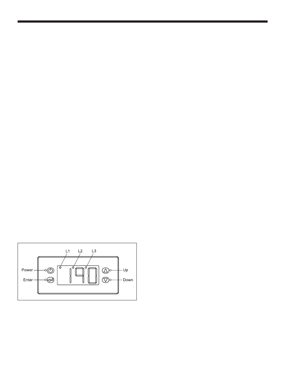
6.1 Front Panel Display
Figure 30
shows the front panel display of the
boiler control. The Endurance boiler control has
four buttons, which are used to access viewing and
programming menus. The LED’s at the top of the
control show the sequence of events, from left to right:
Pump Status, TH Status (boiler attempting to run) and
Gas Valve Status.
There are three LEDs that illuminate at the top
of the controller, shown as L1, L2 and L3 in
Figure
30
. These light from left to right, in order of the events
that happen when the Endurance receives a call for
heat.
L1 (LED on top left of display) lights when the
pump is energized.
L2 (LED in the middle top of display) lights
when the boiler is attempting to light burner.
L3 (LED on the top right of display) lights when
For instance, if the Burner Off Point is chosen as
190°F (88°C), with a fixed 10°F (6°C) differential, the
control will strive to keep the supply temperature at
180°F (82°C).
In this example, when the Endurance gets the
initial call for heat, it will start at low fire, and begin its
heat-up. The control monitors how quickly the supply
temperature is increasing, and bases its modulating
rate (output Btu/hr) on that rate of change. The output
of the unit will reduce as the water temperature
approaches 180°F (80°C). It will attempt to remain at
180°F (80°C) for the entire call for heat. If the system
requires less heat than the lowest modulating rate,
the outlet water temperature will rise past the Burner
Control Point of 180°F (82°C), and will eventually
reach the Burner Off Point of 190°F (88°C) and shut
off.
The control also has a Burner On Point that is
calculated by subtracting the Burner On Differential
from the Burner Control Point. The Burner On
Differential is fixed at 13°F (7°C) on the to ensure that
the tank will always be charged properly for domestic
water calls for heat. In the example here, with a 13°F
(7°C) Burner On Differential, that would mean a
Burner On Point of 167°F (75°C). During a call for
heat, if the Endurance reaches its Burner Off Point,
the control will allow the supply temperature to drop
to the Burner On Point of 167°F (75°C) before it fires
again.
Figure 31
shows a graph of this example.
6.3 View Menu
The boiler control allows the user to view the
temperatures that are being read by the sensors.
The default display for the boiler control is the
supply temperature (defined below). To scroll through
and view the other readings, press the up or down
button.
Figures 32 and 33
show the locations of the
temperature sensors. Temperatures available in the
view menu are:
a. Supply Temperature (shown as the default
display) — The temperature of the water leaving
the boiler heat exchanger.
b. Return Temperature (shown as “rtn”) – The
temperature of the water entering the boiler heat
exchanger. (Note that this is not system return
temperature. It is the inlet to the heat exchanger,
which is system return mixed with boiler outlet
water.)
c. Tank Temperature. The temperature of the water
in the transfer tank.
d. Heat Exchanger Delta T (shown as “dt”) – The
temperature difference between the inlet and
outlet of the boiler heat exchanger.
5. Outdoor Air Temperature (shown as “Oat” when
used) – The temperature at the outdoor air sensor.
Figure 30. Boiler Control.
the gas valve is energized.
6.2 Control Logic
The user sets the Burner Control Point by
programming the Burner Off Point. The boiler
control modulates the burner to keep the boiler outlet
temperature at the boiler control point.
The Burner Off Point minus the Off Point
Differential is the Burner Control Point. The Off Point
Differential is fixed at 10°F (6°C).