LAARS EBP 175 MBTU/h - Installation, Operation and Maintenance Instructions User Manual
Page 15
Endurance
Page 15
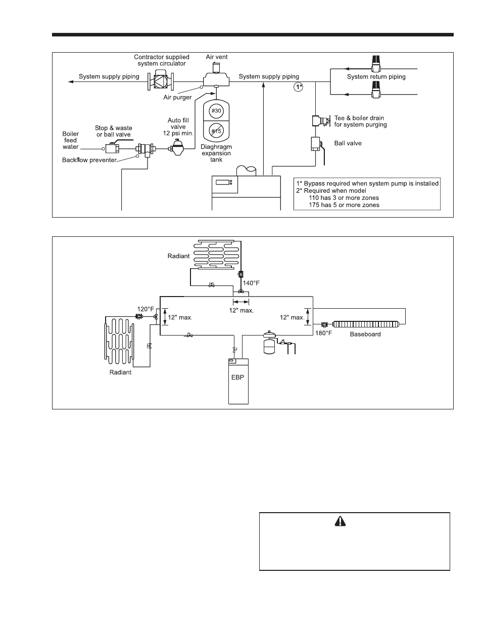
Figure 19. Hydronic Piping with Zone Valves.
Figure 20. Piping, Single Boiler for Multiple Temperature Systems.
providing flow for two heating zones (up to 67 feet
of ¾" baseboard each), and model 175 is capable of
providing flow for four heating zones (up to 67 feet of
¾" baseboard, each).
In radiant systems utilizing 3-way tempering
valves, a bypass pipe must be installed between supply
and return piping.
1. Connect system supply to 1¼" supply connection
marked “SUPPLY”.
2. Pipe the discharge of the relief valve, full size,
to a drain or in a manner to prevent injury in the
event of pressure relief.
3. Install an air purger in flow supply line as shown
in piping diagrams.
4. Install automatic float type air vent on air scoops.
5. Install a diaphragm expansion tank in boiler
outlet piping. To ensure sufficient expansion
volume for the hydronic system water, due to
heat-up and cool-down during normal operation,
a #30 or larger expansion tank must be used on
combo units.
NOTE: Never install expansion tank and auto fill
valve on return.
6. If necessary, install a properly sized circulator
with optional isolation valves in supply beyond
expansion tank.
Caution
To avoid the risk of fire which can result in
property damage, all hot water pipes must be
installed with a minimum 1" (25mm) clearance
from combustible materials.
7. Connect boiler feed water supply with shut off
valve to inlet connection of automatic fill valve.