0 connections, 1 connecting to the rpb-200, 2 connecting to the pxl-250w – Keri Systems RPB-200 User Manual
Page 2: Rpb–200 : rf receiver, Quick start guide rpb–200
RPB–200: RF Receiver
1530 Old Oakland Road, Suite 100
01825-200 Rev. B
San Jose, CA 95112 USA
(800) 260-5265 (408) 451-2520 FAX (408) 441-0309
Web: http://www.kerisys.com E-mail: [email protected]
Page 2 of 8
Quick Start Guide
RPB–200
2.0
Connections
The connection between the PXL controller and the RPB-200 is made through a 7 conductor, shielded, stranded, AWG
24 wire cable (such as Belden 9537 or a larger gauge).
Before running a cable to the RPB-200 you must drill a 1/4 inch diameter hole in the case of the RPB-200 to
accommodate the cable. After the cable has been connected to the RPB-200, the cable/hole can be sealed with a
silicone/RTV type sealer.
2.1
Connecting to the RPB-200
The cable connects to the terminal strip on the RF receiver board, pins 1 through 8 (excluding pins 3 and 6). The cable
shield is not connected at the RPB-200.
2.2
Connecting to the PXL-250W
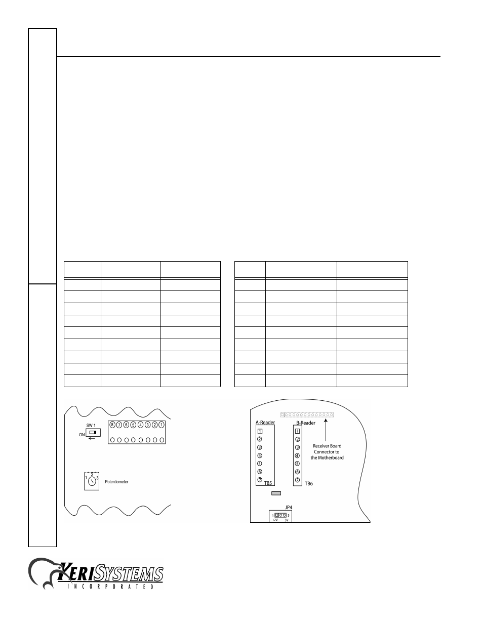
For an "A" reader connection, the cable connects to TB5 pins 1 through 7 (excluding pin 2). For a "B" reader
connection, the cable connects to TB6 pins 1 through 7 (excluding pin 2).
RPB–200 Cable Connections Connecting to the PXL–250W at TB5/TB6
Figure 2: RPB–200 Connections Figure 3: PXL–250W Connections
Pin #
Function
Wire Color
Pin #
Function
Wire Color
1
Ground
Black
4
Ground
Black
–
–
–
4
Shield
Silver
2
Power
Red
3
12V Power
Red
3
no connection
–
2
not used
–
4
Red LED
Brown
6
Red LED
Brown
5
Green LED
Orange
5
Green LED
Orange
6
Yellow LED
–
–
–
–
7
Data 1
White
7
Data 1
White
8
Data 0
Green
1
Data 0
Green