Keri Systems Comm Board User Manual
Comm board, 0 wiring connections, Installation guide
Comm Board
Installation Guide
Page 1 of 3
P/N: 01216-002 Rev. C
The Comm Board provides the external link from master controller to host PC. Comm Boards are only needed for the
master controller for each site. The Comm Board provides communication via either RS-232 serial/direct-connect,
modem, or USB. For Ethernet/LAN communications a LAN-520 is still required (replacing the Comm Board).
NOTE: The Comm Board can be used by any PXL family controller except the PXL-250.
1.0
Wiring Connections
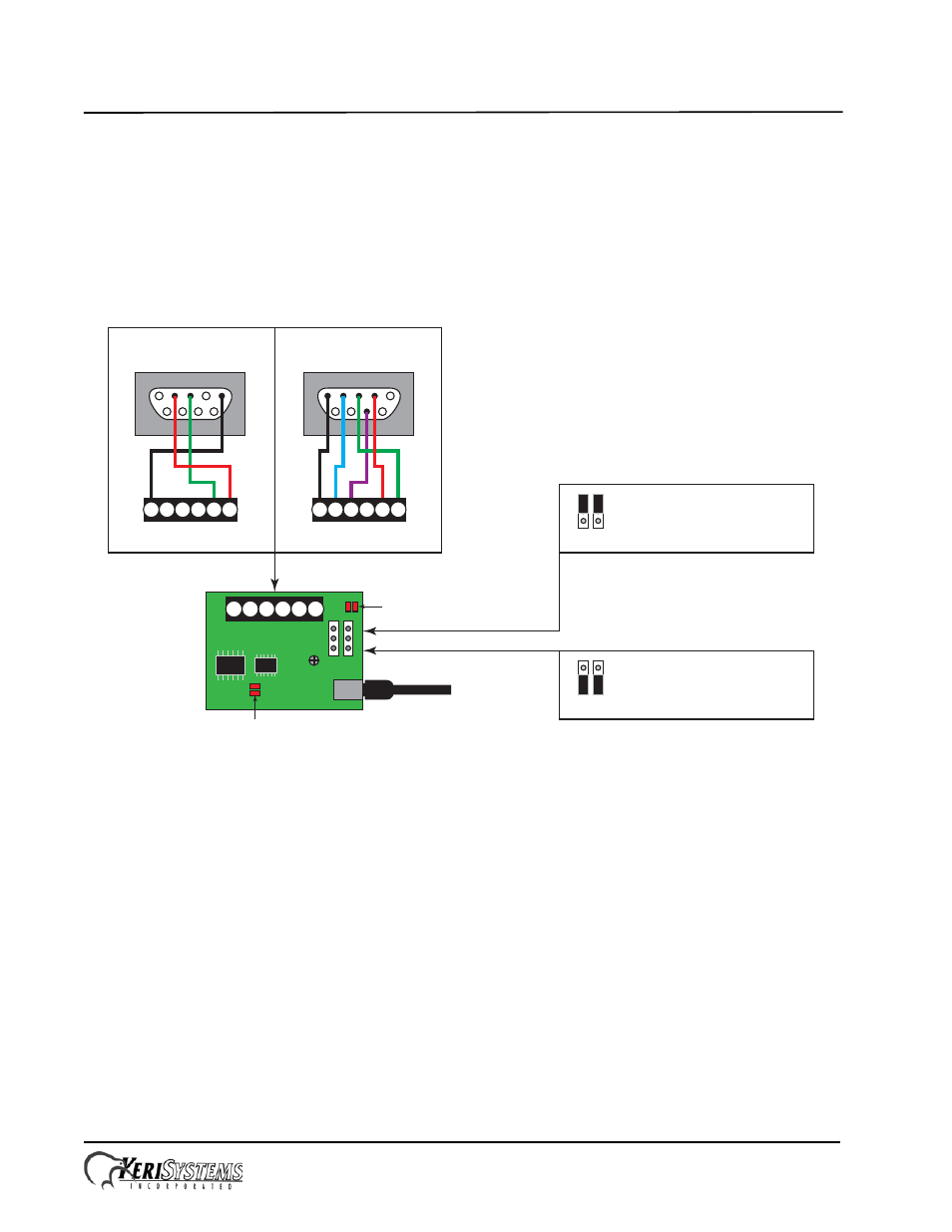
Make your wiring connections per the drawing below.
1.1
USB Communication
The Comm Board is capable of USB serial communication with the host PC using a Mini-B cable. The maximum cable
length from PC to controller is 16 feet (5 meters). Perform the following to set the Comm Board for USB communication:
NOTE: Windows XP operating system screen examples are shown.
1.
On the Comm Board, set JP1 and JP2 per the above drawing.
2.
Plug the Comm Board onto the controller.
3.
Plug the USB cable into the Comm Board.
4.
Power up the controller.
5.
Plug the USB cable into a port on the PC.
6.
Install the USB driver if necessary. This driver will install automatically if there is a connection to the Internet, and is
also included on the software DVD (Drivers\FTDI Driver folder).
7.
Open the Device Manager window:
-
Start > Run > devmgmt.msc
1
2
3
4
5
6
USB Mini-B
Connection
JP1 JP2
JP1 and JP2 on upper pins
for direct-connect serial and
modem communication.
JP1 JP2
JP1 and JP2 on lower pins
for USB to serial communication.
JP1 JP2
D5/D6 - Comm Activity LEDs
USB to Serial
D3/D4 - Comm Activity LEDs
RS-232/Modem
DB-9M
(back side of connector)
Direct-to-PC Connection
Modem Connection
DB-9F
(back side of connector)
1
2
3
4
5
7
1
2
3
4
5
6
2
3
5
1
1
2
3
4
5
6