Communication wiring (continued), Reader wiring, Input circuit wiring – Keri Systems EP1502 User Manual
Page 4
Mercury Security Corporation © 2011
EP1502
DOC 10107-0031
REV 1.05
Page 4
Communication Wiring (continued):
IMPORTANT NOTE! Install the termination jumper ONLY on the panel at each end of the RS-485
bus. Failure to do so will compromise the proper operation of the communication channel!
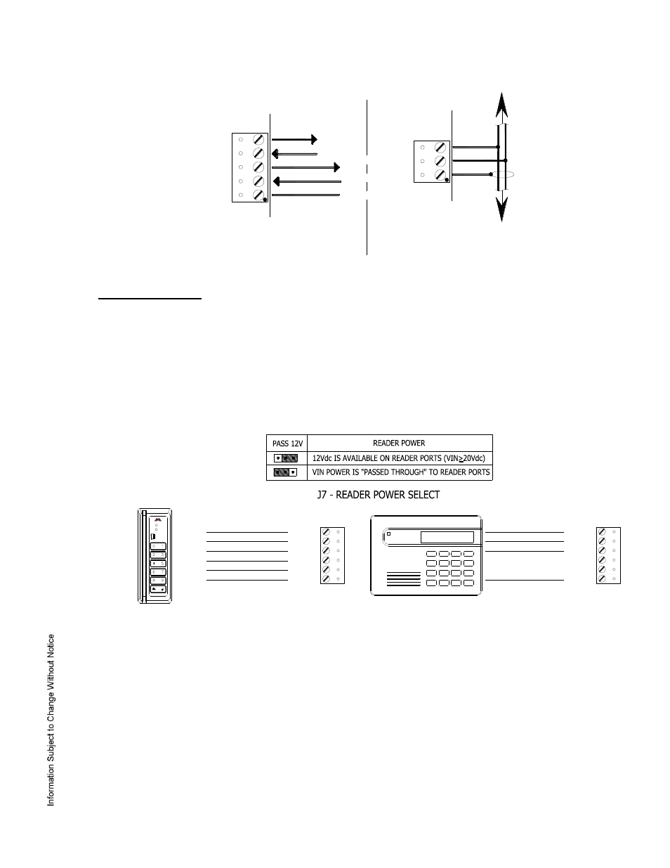
6. Reader Wiring:
Each reader port supports Wiegand, magnetic stripe, and 2-wire RS-485 electrical interfaces. Power
to the reader is selectable: 12 Vdc (VIN must be greater than 20 Vdc), or power is passed-through
(PT) from the input voltage of the EP1502 (TB1-VIN) and is current limited to 150 mA for each reader
port. Readers that require different voltage or have high current requirements should be powered
separately. Refer to the reader manufacture specifications for cabling requirements. In the 2-wire
LED mode the Buzzer output in used to drive the second LED. Reader port configuration is set via
the host software.
DATA1/DATA0 - CLOCK/DATA
2-WIRE RS-485
7. Input Circuit Wiring:
Typically, these inputs are used to monitor door position, request to exit, or alarm contacts. Input circuits
can be configured as unsupervised or supervised. When unsupervised, reporting consists of only the
open or closed states. When configured as supervised, the input circuit will report not only open and
closed, but also open circuit, shorted, grounded*, and foreign voltage*. A supervised input circuit requires
two resistors be added to the circuit to facilitate proper reporting. The standard supervised circuit
requires 1k Ohm, 1% resistors and should be located as close to the sensor as possible. Custom end of
line (EOL) resistances may be configured via the host software.
* Grounded and foreign voltage states are not a requirement of UL 294 and therefore not verified by UL.
RXD
TXD
RTS
CTS
GND
Port 1, RS-232 To Host
TR-
TR+
GND
To serial I/O Devices
TB2
TB3
BLK (6)
ORG (5)
BRN (4)
GRN (2)
RED (1)
WHT (3)
GND
DAT/D0
CLK/D1
BZR
LED
VO
MR-10/20 R
EA
DE
R
TB8 OR TB9
ADDRESS 0
MR-DT
RS-485 MODE
9600 BAUD
READER PORT
2-WIRE RS-485
12Vdc (RED) (1)
TR+ (BLUE) (3)
TR- (GRAY) (4)
GROUND (BLACK) (2)
GND
DAT/D0
CLK/D1
VO
TB8 OR TB9