Pin outs for dcb/wasp pro-4 cables – Kenton Pro-4 User Manual
Page 22
22
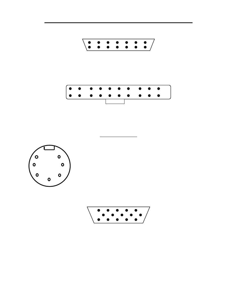
PIN OUTS FOR DCB/WASP PRO-4 CABLES
Juno 60 (and some Jupiter 8s) connector
4 way IEEE plug (viewed from terminals).
1
2
3
4
5
6
7
9
10
11
12
13
14
8
PIN 1 - Busy
PIN 2 - Data
PIN 3 - Clock PIN 4 - Ground
No other pins connected. Insulate the screen at this end.
Other Jupiter 8s connectors
20 pin bump polarised socket (viewed from terminals).
1
2
3
4
5
6
7
8
9
10
11
12
13
14
15
16
17
18
19
20
PIN 7 - Clock PIN 9 - Data
PIN 10 - Ground
PIN 11 - Busy
As this header is an IDC you will need to put a 6 inch length of 16 way IDC ribbon cable
in the header, then join the cables.
Wasp connector
7 pin DIN plug (viewed from terminals).
1 Kybd Data (least significant bit) (0)
2 Kybd Data (Next significant bit) (1)
3 Kybd Data (Next significant bit) (2)
6 7
4 Kybd Data (Next significant bit) (3)
5 1 5 Kybd Data (Next significant bit) (4)
6 Kybd Data (Most significant bit) (5)
4
2 7 Note on trigger
3
PRO-4 DCB/Wasp Connector; (PRO-4 end of cable)
15 way high density D plug (viewed from terminals).
1
2
3
4
5
6
7
8
9
10
11
12
13
14
15
Wasp wiring;
1
Kybd Data (least significant bit) (0) 5
Kybd Data (Next significant bit) (4)
2
Kybd Data (Next significant bit) (1) 6 Kybd Data (Most significant bit) (5)
3
Kybd Data (Next significant bit) (2) 7
NC
(No Connection)
4
Kybd Data (Next significant bit) (3) 8
Note on Trigger
screen all remaining wires, (insulate screen).
DCB wiring;
12 busy
14 clock
13 data
15 ground
No other pins connected for DCB (only for Wasp)