Venting runs – Vermont Casting NVC43 User Manual
Page 9
9
NVC Series B-Vent
20000194
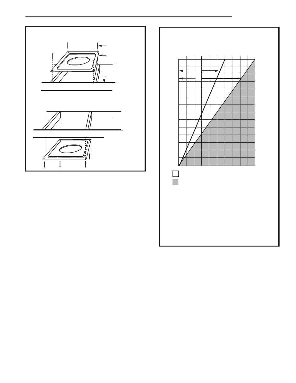
Fig. 9 Firestop/draftstop positions.
Ceiling Installation
FP384
FIRESTOP
11/21/96
adapted from IGF53
Attic Installation
Firestop position when area above ceiling is an attic.
Firestop position when area above ceiling is NOT an attic.
(Firestop/draftstop
appearances may
vary. Only 1 firestop
required per frame.)
Firestop
Spacer
Nails (4)
Joist
FP384
Table 1 Venting configurations.
FP567a
NVBR/NVBC VENTING RUNS
11/12/97
Venting Runs
40
38
36
34
32
30
28
26
24
22
20
18
16
14
12
8 9 10 11 12
3 4 5 6 7
Horizontal Run (in feet)
Ve
rtical Run (in feet)
(Measured from floor of unit tocenter of hor
izontal v
ent pipe
.)
A
A: Vertical installations up to 40 feet (12m) in
height. Up to a 8 ft. horizontal vent run can be
installed within the vent system using a
maximum of two 90-degree elbows or four
45-degree elbows.
B: Vertical installations up to 40 feet (12m) in
height. Up to a 12 ft. horizontal vent run can be
installed within the vent system using a
maximum of two 45-degree elbows.
B
= Acceptable venting configuration
= Unacceptable venting configuration
FP567a