50c r – Carrier 50CR User Manual
Page 13
13
228
= 1 v
229
= 2 v
227
= 2 v
LEGEND
FLA
— Full Load Amps
LRA
— Locked Rotor Amps
MCA --
Minimum Circuit Amps
MOCP
—
Maximum Overcurrent Protection
RLA
— Rated Load Amps
NO TES:
1. In compliance with NEC (National Electrical Code) requirements
for multimotor and combination load equipment (refer to NE C
Articles 430 and 440), the overcurrent protective device for the
unit shall be Power
Supply fuse. The CGA (Canadian Gas
Association) units may be
fuse or circuit break
er.
2. Minimum wire size is based on 60 C copper wire. I f other than
60 C wire
is used, or if length exceeds wire length in table,
determine siz e from NEC.
.
3. Unbalanced 3-Phase Supply Voltage
Never operate a motor where a phase imbalance in supply volt-
age is greater than 2%. Use the following formula to determine
the percentage of voltage imbalance.
% Voltage imbalance
max voltage deviation from average voltage
= 100 x
average voltage
EXAMPLE: Supply voltage is 230-3-60.
AB = 228 v
BC = 231 v
AC = 227 v
228 + 231 + 227
Average Voltage =
3
686
=
3
= 229
Determine maximum deviation from average voltage.
(AB) 229 -
(BC) 231 -
(AC) 229 -
Maximum deviation is 2 v.
Determine percent of voltage imbalance.
2
% Voltage Imbalance = 100 x
229
= 0.8%
This amount of phase imbalance is satisfactory as it is below the
maximum allowable 2%.
IMPORTANT: If the supply voltage phase imbalance is
more than 2%, contact your local electric utility company
immediately.
®
*
Heater capacity (kW) based on heater voltage of 208v & 240v.
If power distibution voltage to unit varies from rated heater
voltage, heater kW will vary accordingly.
C03014
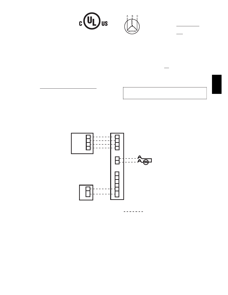
Fig. 13 -- Electrical Data Legend
LEGEND
Field Control-Voltage Wiring
D
C
B
A
User Interface
D
C
B
A
Infinity Control Board
OA
T
R
Y
O
W
C
HUM
C
Humidifier
(Optional)
24v
ac
Outdoor Air Thermistor
(if used)
A05302
Fig. 14 -- Control Voltage Wiring Connections
50C
R