Warning, Caution – Carrier 50CR User Manual
Page 11
11
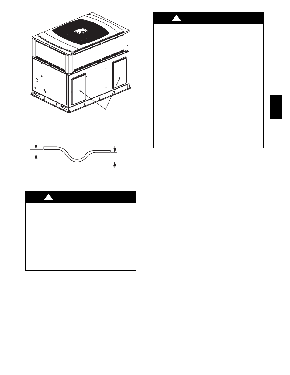
Duct Covers
A05301
Fig. 11 -- 50CR with Duct Covers On
1” (25mm) MIN.
2” (50mm) MIN.
TRAP
OUTLET
C99013
Fig. 12 -- Condensate Trap
Step 7—Install Electrical Connections
ELECTRICAL SHOCK HAZARD
Failure to follow this warning could result in personal injury
or death.
The unit cabinet must have an uninterrupted, unbroken
electrical ground to minimize the possibility of personal injury
if an electrical fault should occur. This ground may consist of
an electrical wire connected to the unit ground screw in the
control compartment, or conduit approved for electrical
ground when installed in accordance with NEC, ANSI/NFPA
American National Standards Institute/National Fire
Protection Association (latest edition) (in Canada, Canadian
Electrical Code CSA C22.1) and local electrical codes.
!
WARNING
HIGH--VOLTAGE CONNECTIONS
The unit must have a separate electrical service with a
field--supplied, waterproof disconnect switch mounted at, or within
sight from the unit. Refer to the unit rating plate, NEC and local
codes for maximum fuse/circuit breaker size and minimum circuit
amps (ampacity) for wire sizing (See Table 2 for electrical data).
The field--supplied disconnect may be mounted on the unit over the
high--voltage inlet hole (See Fig. 6 and 7).
If the unit has an electric heater, a second disconnect may be
required. Consult the Installation, Start--Up, and Service
Instructions provided with the accessory for electrical service
connections.
Operation of unit on improper line voltage constitutes abuse and
may cause unit damage that could affect warranty.
UNIT COMPONENT DAMAGE HAZARD
Failure to follow this caution may result in damage to the unit
being installed.
1. Make all electrical connections in accordance with NEC
ANSI/NFPA (latest edition) and local electrical codes
governing such wiring. In Canada, all electrical
connections must be in accordance with CSA standard
C22.1 Canadian Electrical Code Part 1 and applicable local
codes. Refer to unit wiring diagram.
2. Use only copper conductor for connections between
field--supplied electrical disconnect switch and unit. DO
NOT USE ALUMINUM WIRE.
3. Be sure that high--voltage power to unit is within operating
voltage range indicated on unit rating plate. On 3--phase
units, ensure phases are balanced within 2 percent. Consult
local power company for correction of improper voltage
and/or phase imbalance.
4. Insulate low--voltage wires for highest voltage contained
within conduit when low--voltage control wires are in same
conduit as high--voltage wires.
5. Do not damage internal components when drilling through
any panel to mount electrical hardware, conduit, etc.
!
CAUTION
ROUTING POWER LEADS INTO UNIT
Use only copper wire between disconnect and unit. The high
voltage leads should be in a conduit until they enter the duct panel;
conduit termination at the duct panel must be watertight. Run the
high--voltage leads through the power entry knockout on the power
entry side panel. See Fig. 6 and 7 for location and size. For
single--phase units, connect leads to the black and yellow wires ; for
3--phase units, connect the leads to the black, yellow, and blue wires.
CONNECTING GROUND LEAD TO GROUND SCREW
Connect the ground lead to the chassis using the ground screw in the
wiring splice box (See Fig. 14 and 17).
ROUTING CONTROL POWER WIRES
For detailed instruction on the low voltage connections to the User
Interface (UI), refer to the UI installation guide.
Form a drip--loop with the control leads before routing them into the
unit. Route the low voltage control leads through grommeted,
low--voltage hole provided into unit (See Fig. 6 and 7). Connect user
interface leads to unit control power leads as shown in Fig. 14.
The unit transformer supplies 24--v power for complete system
including accessory electrical heater. A fuse is provided in the 24--v
circuit on the control board (See Fig. 19); see the caution label on
the transformer. Transformer is factory wired for 230--v operation.
If supply voltage is 208--v, rewire transformer primary as described
in Special Procedures for 208--v Operation section.
50C
R