360dvs series direct vent fireplaces, Fuel conversion instructions – Vermont Casting 360DVSL User Manual
Page 31
31
360DVS Series Direct Vent Fireplaces
10006326
Fuel Conversion Instructions
To convert this appliance from gas type to another,
follow these instructions. Before proceeding, turn
control knob to “OFF” and turn gas supply OFF. Turn
OFF any electricity that may be going to the appliance.
CAUTION: Logs may be HOT! Allow to cool before
proceeding.
This conversion procedure must be
carried out by an authorized service
provider.
1. Disconnect power to unit and shut off the gas supply.
2. Remove window frame assembly (see “Window
Frame Assembly Removal” Section).
3. Carefully remove the logs and lava rock material.
4. Remove the screws holding the burner housing
assembly in place.
5. Remove the burner housing assembly. On some
models you may need to loosen the pilot bracket
retaining screw/nut, and tilt the pilot and bracket
assembly to gain sufficient clearance to remove the
burner housing assembly.
6. Remove front and rear orifice and replace with
orifice supplied in the conversion kit.
NOTE: On 360DV/S2/S3/SL/SR, both burner orifices
are the same size.
7. Remove the screws holding the air shutter to the
burner tubes. (Fig. 46) Note the alignment of the air
shutter on the tubes. Remove the air caps and
replace them with the new air shutters supplied in
the conversion kit.
Air Shutter
Retaining Screws
Air Shutters
FP1447
Fig. 46 Air shutter adjustment.
8. SIT Top Convertible Pilot
Gently lift off pilot hood from the pilot. NOTE: Do not
remove the spring clip holding the hood in place.
Using a correctly-sized Allen key, unscrew the
exposed orifice. Insert the new orifice supplied in the
kit; do not overtighten the orifice. Replace the pilot
hood ensuring the index tab aligns with the notch on
the hood.
PSE Pilot
Using a suitable wrench on hexagonal body, un-
screw the pilot hood assembly from the pilot. Do not
twist the hood itself. Remove the orifice and replace
it with the new orifice supplied in the kit. Refit the
pilot hood assembly. Do not overtighten the pilot
hood. The hood must return to its original alignment.
Take care not to damage the thermocouple, thermo-
pile or igniter.
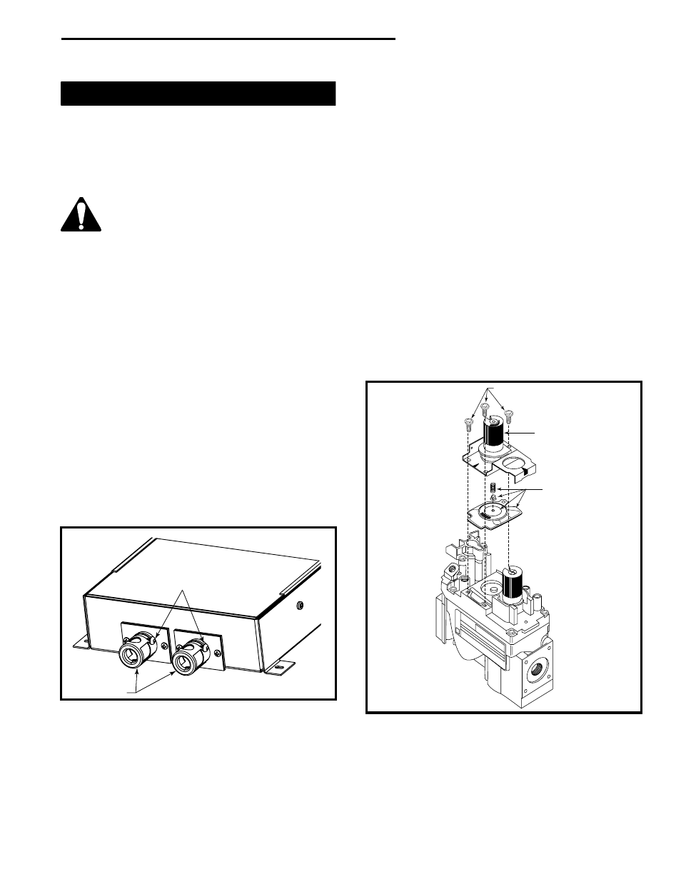
9. SIT 820 NOVA Gas Control Valve (Fig. 47)
a) Using a Torx T20 or slotted screwdriver, remove
and save three (3) pressure regulator mounting
screws (A), pressure regulator tower (B), and
diaphragm (C).
b) Ensure the rubber gasket (D) is properly posi-
tioned and install the new HI/LO pressure regulator
to the valve using the new screws (E) supplied with
the kit. Tighten the screws securely. (Reference
torque: 25 in.lb.)
c) Install the enclosed identification label (F) to the
valve body where it can be easily seen.
A
B
C
OFF
PIL
O T
ON
FC107
Fig. 47 Remove mounting screws, pressure regulator tower
and diaphragm assembly.