360 dvs series direct vent fireplaces, Vertical through-the-roof application – Vermont Casting 360DVSL User Manual
Page 20
20
360 DVS Series Direct Vent Fireplaces
10006326
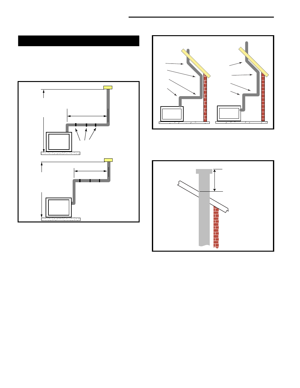
Vertical Through-the-Roof Application
This Gas Fireplace has been approved for:
•
Vertical installations up to 40’ (12m) in height. Up to
a 10’ (3m) horizontal vent run can be installed within
the vent system using a maximum of two 90
°
elbows. (Fig. 30)
Max. Height 40’
(12.2m)
Min. Height 8’
(2.4m)
Max. 10’ (3m)
Support Straps
Every 36”
(914mm)
Max. 10’ (3m)
Max. Height
40’ (12.2m)
Min. Height
8’ (2.4m)
FP1443
Fig. 30 Support straps for horizontal runs.
•
Up to two 45
°
elbows may be used within the
horizontal run. For each 45
°
elbow used on the
horizontal level the maximum horizontal length must
be reduced by 18” (457mm).
Example: Maximum horizontal length:
Zero elbows
= 10’ (3m)
1 x 45
°
elbows
= 8
¹⁄₂
’ (2.6m)
2 x 45
°
elbows
= 7’ (2.1m)
•
A minimum of an 8 ft. (2.43 m) vertical rise.
•
Two (2) sets of 45
°
elbow offsets may be used
within the vertical sections. From zero to max 8 ft.
(2.43 m) vent pipe can be used between elbows.
(Fig. 30)
•
7DVCS supports offsets. (Fig. 33) This application
will require you first determine the roof pitch and
use the appropriate starter kit. See Venting Compo-
nents List, Page 22.
•
The maximum angular variation allowed in the
system is 270˚. (Fig. 31)
1
2
3
4
1
2
3
4
1 + 2 + 3 + 4 = 270
°
FP1445
Fig. 31 Maximum elbow usage.
•
The minimum height of the vent above the highest
point of penetration through the roof is 2’ (610mm).
(Fig. 32)
Min.
2’ (610 mm)
FP1185
Fig. 32 Maximum termination to roof clearance.