Carrier 38AKS028-044 User Manual
Page 4
Receiver —
No receiver is provided with the unit; it is
recommended that one not be used.
Piping Procedure —
Do not remove run-around pipe
from suction and liquid line stubs until piping connections
are ready to be made. Pass nitrogen or other inert gas through
piping while brazing, to prevent formation of copper oxide.
Install field-supplied thermostatic expansion valve (TXV)
in liquid line ahead of each evaporator section. For 2-stage
cooling, the field-supplied capacity control solenoid used must
be wired to be opened by control from a 2-stage thermostat.
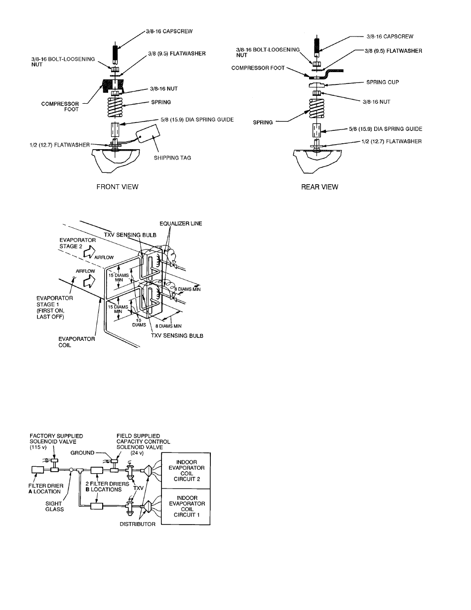
SUCTION PIPING AT EVAPORATOR AND TXV BULB
LOCATION (See Fig. 5) — The purpose of these recom-
mendations is to achieve good mixing of the refrigerant leav-
ing the evaporator suction header for proper sensing by the
TXV bulb.
1. A minimum of two 90° elbows must be installed up-
stream of the expansion valve bulb location.
2. The TXV sensing bulb should be located on a vertical
riser where possible. If a horizontal location is necessary,
secure the bulb at approximately the 4 o’clock position.
3. Size the suction line from the evaporator through the riser
for high velocity. Enter the suction pipe sizing charts in
the Carrier System Design Manual at design tons and equiva-
lent length (for 2° F [1.1° C] loss). If reading falls be-
tween 2 sizes on chart, choose the smaller pipe size.
Suction piping for the high velocity section should be
selected for about 0.5° F (0.3° C) friction loss. If a 2° F
(1.1° C) loss is allowed for the entire suction line, 1.5° F
(0.8° C) is left for the balance of the suction line, and it should
be sized on that basis. Check that the high-velocity sizing
is adequate for oil return up the riser.
If an oil return connection at the bottom of this suction
header is supplied with an evaporator, this connection must
be teed-in ahead of first mixing elbow. When the compres-
sor is below the evaporator, the riser at the evaporator does
not have to extend as high as the top level. After a
15-diameter riser has been provided, the suction line may
elbow down immediately.
SAFETY RELIEF — A fusible plug is located on unit liquid
line before the liquid valve.
NOTE: All dimensions are in inches (mm).
Fig. 3 — Compressor Mounting
TXV — Thermostatic Expansion Valve
NOTES:
1. Suction line is connected to coil on same side as the entering air.
2. Lower section is first on and last off.
3. For more complete piping information, refer to Carrier System
Design Manual, Part 3.
TXV — Thermostatic Expansion Valve
Fig. 5 — Liquid Line Solenoid Valve,
Filter Drier(s) and Sight Glass Locations
Fig. 4 — Suction Line Piping to Unit
with 2 Section Coil Split
4