Oil pressure safety switch (ops), Compressor protection, High-pressure switch – Carrier 38AKS028-044 User Manual
Page 20: Low-pressure switch, Winter start control, Head pressure control
Oil Pressure Safety Switch (OPS) —
The OPS in
the control circuit stops the compressor and unit, if proper
oil pressure differential is not established at start-up or main-
tained during operation. If OPS stops the unit, determine the
cause and correct before restarting unit. Failure to do so will
constitute abuse. Equipment failure due to abuse may void
the warranty.
Compressor Protection
CIRCUIT BREAKER — Calibrated trip manual reset, am-
bient compensated, magnetic breaker protects against motor
overload and locked rotor conditions.
CONTROL MODULE TIMER — This control protects com-
pressor against short cycling. See Sequence of Operation on
page 17.
CRANKCASE HEATER — This minimizes absorption of
liquid refrigerant by oil in crankcase during brief or ex-
tended shutdown periods.
IMPORTANT: Never open any switch or disconnect
that deenergizes the crankcase heater unless unit is be-
ing serviced or is to be shut down for a prolonged pe-
riod. After a prolonged shutdown on a service job, en-
ergize the crankcase heater for 24 hours before starting
the compressor.
High-Pressure Switch —
This switch has fixed, non-
adjustable settings. Switch is mounted on the compressor (See
Table 4).
Low-Pressure Switch —
This switch has fixed, non-
adjustable settings. Switch is mounted on the compressor.
(See Table 4.)
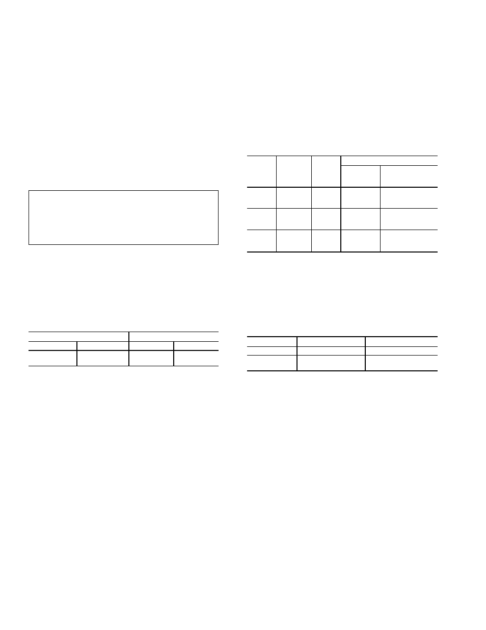
Table 4 — Pressure Switch Settings, psig (kPa)
HIGH PRESSURE
LOW PRESSURE
Cutout
Cut-in
Cutout
Cut-in
426 ± 7
(2937 ± 48)
320 ± 20
(2206 ± 138)
27 ± 3
(186 ± 21)
44 ± 5
(303 ± 34)
Winter Start Control —
Bypass relay timer bypasses
low-pressure switch for 2 minutes on unit start-up.
Head Pressure Control —
Control maintains ad-
equate discharge pressure under low ambient temperature con-
ditions. See Table 5.
FAN CYCLING — These 38AKS units have standard pro-
vision for fully automatic intermediate-season head pressure
control through condenser fan cycling. Fan no. 2 is cycled
by a fan cycling pressure switch (FCPS) which responds to
variation in discharge pressure. The pressure sensor is lo-
cated in the liquid line of the refrigerant circuit. Fan no. 3
cycling is controlled by outdoor-air temperature through an
air temperature switch (ATS) (38AKS044 units only).
Table 5 — Minimum Outdoor-Air
Operating Temperature
UNIT
38AKS
COMPR
CAP. (%)
COND
TEMP,
F (C)
MIN OUTDOOR TEMP, F (C)
Standard
Unit
Low Ambient
Control
(Motormaster
ா
)
028
100
90 (32)
31 (–1)
–20 (–29)
67
80 (27)
35 (2)
–20 (–29)
33
70 (21)
43 (6)
–20 (–29)
034
100
90 (32)
30 (–1)
–20 (–29)
67
80 (27)
34 (1)
–20 (–29)
33
70 (21)
42 (6)
–20 (–29)
044
100
90 (32)
25 (–4)
–20 (–29)
67
80 (27)
30 (–1)
–20 (–29)
33
70 (21)
35 (2)
–20 (–29)
The ATS is located in the lower divider panel between the
compressor compartment and condenser section. Through a
hole in the panel, the sensing element is exposed to air en-
tering the no. 1 fan compartment. Fan no. 1 is noncycling.
Table 6 shows the operating settings of the FCPS and the
ATS.
Table 6 — Fan Cycling Controls
CONTROL BY
SWITCH OPENS
SWITCH CLOSES
Temp, F (C)
70 ± 3 (21 ± 1.7)
80 ± 3 (27 ± 1.7)
Pressure,
psig (kPa)
160 ± 10 (1103 ± 69)
260 ± 15 (1793 ± 103)
NOTE: See Fig. 6 and 7 for fan arrangement.
20