Carrier 50TCQA User Manual
Page 8
8
Positioning on Curb —
Position unit on roof curb so that the following clearances
are maintained:
1
/
4
in. (6.4 mm) clearance between the
roof curb and the base rail inside the front and rear, 0.0 in.
clearance between the roof curb and the base rail inside on
the duct end of the unit. This will result in the distance
between the roof curb and the base rail inside on the
condenser end of the unit being approximately equal to
Fig. 3, section C--C.
Although unit is weatherproof, guard against water from
higher level runoff and overhangs.
After unit is in position, remove the compressor access
panel. Holding the blocking between compressors with
one hand, cut the strapping. Carefully remove the
blocking without damaging tubing, wiring, or controls.
Remove the strapping and replace the access panel.
Remove all shipping materials and top skid. Recycle or
dispose of all shipping materials.
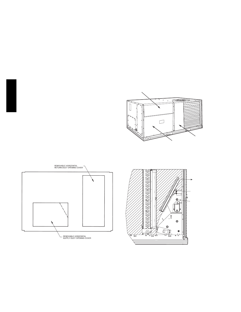
Step 7 — Convert to Horizontal and Connect
Ductwork (when required)
Unit is shipped in the vertical duct configuration. Unit
without factory--installed economizer or return air smoke
detector option may be field--converted to horizontal
ducted
configuration.
To
convert
to
horizontal
configuration, remove screws from side duct opening
covers and remove covers. Using the same screws, install
covers on vertical duct openings with the insulation--side
down. Seals around duct openings must be tight. See
Fig. 6.
C06108
Fig. 6 -- Horizontal Conversion Panels
Field--supplied flanges should be attached to horizontal
duct openings and all ductwork should be secured to the
flanges. Insulate and weatherproof all external ductwork,
joints, and roof or building openings with counter flashing
and mastic in accordance with applicable codes.
Do not cover or obscure visibility to the unit’s informative
data plate when insulating horizontal ductwork.
Step 8 — Install Outside Air Hood
Economizer Hood Removal and Setup -- Factory
Option
1. The hood is shipped in knock--down form and
located in the return air compartment. It is attached
to the economizer using two plastic tie--wraps.
2. To gain access to the hood, remove the filter access
panel. (See Fig. 7.)
3. Locate and cut the (2) plastic tie--wraps, being
careful to not damage any wiring. (See Fig. 8.)
4. Carefully lift the hood assembly through the filter
access opening and assemble per the steps outlined
in Economizer Hood and Two–Position Hood on
page 10.
FILTER ACCESS PANEL
OUTDOOR-AIR OPENING AND
INDOOR COIL ACCESS PANEL
COMPRESSOR
ACCESS PANEL
C06023
Fig. 7 -- Typical Access Panel Locations
Economizer
Cut Plastic Ties
(2) Places
Remove Hood Parts
C08633
Fig. 8 -- Economizer Wiring
50TC
Q
A