Carrier 50TCQA User Manual
Page 35
35
downward, into the return air stream. The sampling tube is
connected via tubing to the return air sensor that is
mounted on a bracket high on the partition between return
filter and controller location. (This sensor is shipped in a
flat--mounting location. Installation requires that this
sensor be relocated to its operating location and the tubing
to the sampling tube be connected. See “Completing
Installation of Return Air Smoke Sensor:” for details.)
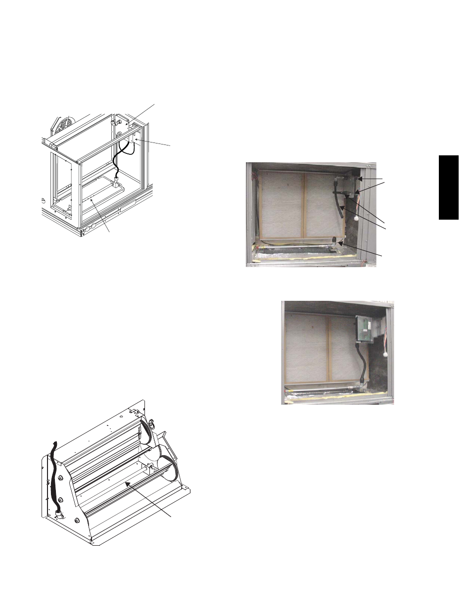
Return Air Detector Sampling Tube
Controller module
Return Air Detector module
(shipping position shown)*
*RA detector must be moved from shipping position to operating position by installer
C07307
Fig. 61 -- Typical Return Air Detector Location
Return Air with Economizer — The sampling tube is
inserted through the side plates of the economizer
housing, placing it across the return air opening on the
unit basepan. See Fig. 61. The holes in the sampling tube
face downward, into the return air stream. The sampling
tube is connected via tubing to the return air sensor that is
mounted on a bracket high on the partition between return
filter and controller location. (This sensor is shipped in a
flat--mounting location. Installation requires that this
sensor be relocated to its operating location and the tubing
to the sampling tube be connected. See the following
installation procedure.)
Return Air
Sampling Tube
C08129
Fig. 62 -- Return Air Sampling Tube Location
Completing Installation of Return Air Smoke
Sensor:
1. Unscrew the two screws holding the Return Air
Sensor detector plate. See Fig. 63. Save the screws.
2. Remove the Return Air Sensor and its detector plate.
3. Rotate the detector plate so the sensor is facing out-
wards and the sampling tube connection is on the bot-
tom. See Fig. 64.
4. Screw the sensor and detector plate into its operating
position using screws from Step 1. Make sure the
sampling tube connection is on the bottom and the ex-
haust tube is on the top. See Fig. 64.
5. Connect the flexible tube on the sampling inlet to the
sampling tube on the basepan.
Flexible
Exhaust Tubes
Screws
Sample Tube
C08126
Fig. 63 -- Return Air Detector Shipping Position
C08127
Fig. 64 -- Return Air Sensor Operating Position
Additional Application Data — Refer to Catalog No.
HKRNKA--1XA for discussions on additional control
features of these smoke detectors including multiple unit
coordination.
50TC
Q
A