Installation of heater assembly in tank (cont’d.) – Chromalox FXTH PN401 User Manual
Page 5
INSTALLATION OF HEATER ASSEMBLY IN TANK (cont’d.)
G. Carefully unwind and straighten thermostat capillary tube. The
capillary must be reasonably straight. Be absolutely certain the
bulb is seated at bottom of well. Carefully coil any excess capil-
lary and position next to thermostat and away from electrical con-
nections. Repeat same procedure if low limit alarm is provided.
Attach wire for overtemperature sensor to terminals.
NOTE: Over-temperature control is located in the Chromalox
Control Center. If heater is supplied without control center, be
sure to obtain an over-temperature control for a positive thermis-
tor, otherwise heater will be without over-temperature protection.
H. If the low temperature thermostat is being used, connect annunci-
ator leads directly to terminals on this thermostat and provide an
independent power source. The switch rating is; 20 amp @ 115V,
15 amp @ 230V, pilot duty 125VA.
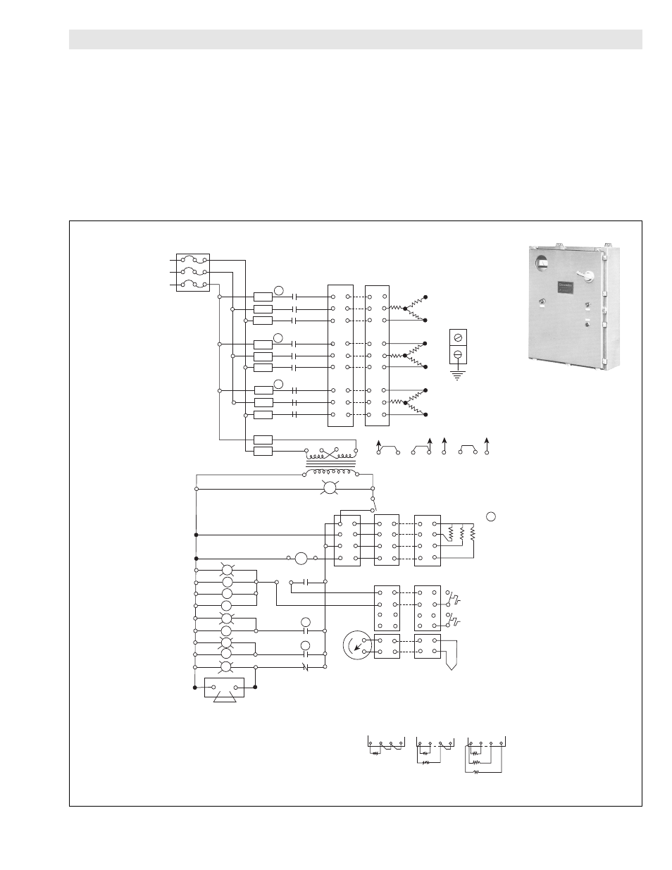
I. If temperature indicator is employed, wire in accordance with
Figure J. Use wire size as recommended for connecting to control
center.
J. Install control wiring through 3/4" conduit connection as indicat-
ed on page 1. Leave lid off' terminal housing until operational
check is completed. Install breather tube on the outside of the ter-
minal box as shown on page 1, Make sure top of tube is at least
12" above the drainage water level. CAUTION: All conduit con-
nections to terminal housing must be sealed to prevent entry of
any water, water vapor or condensation into terminal housing.
Breather tube length may be cut to shorten height, or extended for
higher flood levels by using 3/8” compression tube coupling and
3/8” tubing, as desired between formed breather tube and elbow
fitting on side of terminal housing.
Temperature
Indicator (Optional)
Low Temp. Alarm
Contacts (Optional)
Non-Indicating
Temp. Control
4
Overtemp.
Probes
Terminal
Block
8
7
6
5
8
7
6
5
8
7
6
5
4
3
2
1
Terminal
Block
Overtemp.
Control
1CR
1CR
2 TDR
1 TDR
Heat
Htr. Contactor #1
#1 Time Delay Relay(15 Sec.)
#2 Time Delay Relay(30 Sec.)
Heat
Heater Contactor #2
Heat
Heater Contactor #3
Overtemp.
Control Relay
Power On
X2
X1
G
ISS
Off - On
Control
H4 H2 H3
H1
H4
H2 H3 H1 H4
H2
H3
H1
240V
480V
BL1
BL2
BL3
CL1
CL2
CL3
Ground
C3
C2
3
2
C1
1
AL1
AL2
AL3
Terminal
Blocks
Fuses
Circuit
Breaker
L1
L2
L3
IL3
IL2
IL1
1 TDR 2
3
2 TDR
1CR
A1
A2
Audible Alarm
(Optional)
Thermistors located on heater with leads in conduit riser.
One thremistor per heater tube.
1 Heater
3 Heaters
2 Heaters
1. Contactor “1 CON” and no fuses are supplied on single stage models.
2. Used on two stage models - fuses “3FU thru 8FU” - Contactor
“2 Con” - Time delay relay “1TDR” - Pilot light “3LT”.
3. Used on three stage models - fuses “3FU thru 11FU” - Contactor
“2 Con & 3 Con” - Time delay relay “1TDR & 2TDR” - Pilot
lights “3LT and 4LT”.
4. Termistor connections: Necessary Jumpers - Factory Wired
NOTES:
F8
F3
F4
F5
F6
F7
C3
R
A
C2
A
C1
A
F2
F1
F10
F11
F9
OCC & WCC Control Center
5
Figure J