Changing friction wheel – Cub Cadet 933 SWE User Manual
Page 17
17
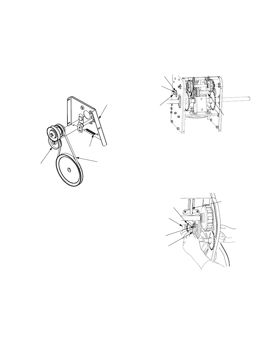
Drive Belt
•
Repeat the first five steps from the above "Auger
Belt" sub-section to split the snow thrower.
•
Pull the idler pulley away from the backside of the
drive belt to relieve the tension and slide the drive
belt off the idler pulley (If necessary unhook the
extension spring from the belt cover plate). See
Figure 22.
•
Roll the drive belt off the lower drive pulley and
remove the belt from the engine pulley.
•
Install the new belt on the pulleys in the reverse
order and re-tension with the idler pulley.
Figure 22
•
Reinstall the auger drive belt and connect the auger
idler arm following the instructions in the previous
sub-section.
•
Reassemble the two halves of the unit hooking the
lower portion of the auger housing over the
stationary shoulder bolts in the frame assembly.
•
Secure the two halves with the two bolts and lock
washers removed earlier.
•
Slip the auger control belt over engine pulley.
•
Attach the “Z” fitting of the cable into the brake
bracket assembly. Refer to Figure 20.
•
Reinstall the shoulder bolt and lock washer on the
left side of the engine pulley, and reinstall the belt
cover.
•
Position the chute crank rod and reinstall the flat
washer and internal cotter pin.
Changing Friction Wheel
The friction wheel is subject to wear and should be
checked after the first 25 hours of operation, and
periodically thereafter. Replace the friction wheel if any
signs of wear or cracking are found.
•
Drain the gasoline from the snow thrower, or place
a piece of plastic under the gas cap.
•
Tip the snow thrower up and forward, so that it rests
on the housing.
•
Remove the six screws from the frame cover
underneath the snow thrower.
•
Remove the right wheel(s) from the axle.
•
Using a 3/4” wrench to hold the hex shaft, loosen
but do not fully remove the hex screw from the left
side of the frame. See Figure 23.
Figure 23
•
Gently tap the head of the hex screw to drive the
bearing on the right end of the hex shaft out of the
frame housing; then remove the hex screw and
belleville washer.
•
Carefully pull the hex shaft out from the right side of
the frame to slide the spacer and sprocket from the
left end of the hex shaft. The sprocket should
remain hanging lose in the chain. See Figure 24.
Figure 24
•
After noting where the pin of the shift arm assembly
is inserted into the friction wheel assemble, hold the
friction wheel and continue to pull the hex shaft
from the right side of the frame until friction wheel
can be removed from the shaft.
•
Lift the friction wheel assembly out between the
axle support bracket and the steering shaft
assemblies.
Drive Belt
Extension
Spring
Belt Cover Brkt.
Idler
Pulley
Hex Shaft
Hex Screw
Belleville
Washer
Bearing
Shift Arm
Assembly
Pin
Friction
Wheel
Sprocket
Spacer