Cub Cadet 933 SWE User Manual
Page 16
16
•
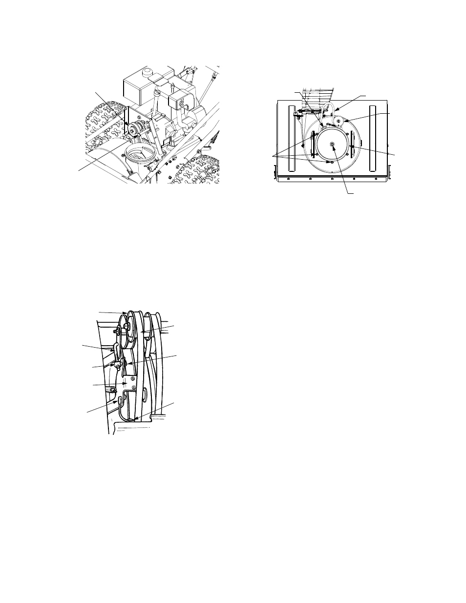
Remove the large shoulder bolt and washer on the
left hand side of the engine pulley. See Figure 19.
Figure 19
Auger Belt
NOTE: Reference to right hand or left hand side of the
machine are observed from the operating position.
•
Remove the internal cotter pin and flat washer from
the ferrule in order to disconnect the auger idler rod
from the brake bracket assembly. See Figure 20.
•
Slip the auger drive belt (the front belt) off the
engine pulley. See Figure 20.
•
Pull the brake bracket assembly towards the cable
guide roller and unhook the auger cable “Z” fitting.
Figure 20
•
Use a 9/16” wrench to remove the upper bolts and
lock washers that secure the rear of the auger
housing to the frame . Refer to Figure 18.
•
Separate the auger housing from the frame by
tilting the housing forward and pulling up the
handles.
•
Using a 1/2” wrench, remove the hex screw and
belleville washer from the center of the pulley on
the auger housing. Lift the brake bracket assembly
out of the pulley groove and remove the pulley. Be
careful not to lose the hi-pro key from the center of
the pulley. See Figure 21.
•
Place the new auger belt in the pulley groove.
Position the pulley and belt inside the belt keepers
on the rear of the auger housing. See Figure 21.
Figure 21
•
Align the keyway of the pulley with the hi-pro key,
lift the brake bracket assembly, and push the pulley
fully onto auger gear box input shaft. Secure with
the hex screw and belleville washer (cupped side
toward the pulley). The brake puck must be seated
in the pulley groove.
•
Insert the ferrule on the auger idler rod into the
brake bracket assembly and secure with the flat
washer and internal cotter pin. Check for proper
adjustment.
Proper Adjustment: With the auger clutch lever in the
disengaged position, the top surface of the new belt
should be even with the outside diameter of the pulley.
•
To adjust, remove the auger idler arm ferrule from the
brake bracket and thread the ferrule in (towards idler
pulley) to increase tension on belt, or out to decrease
tension.
NOTE: The brake puck must always be firmly seated in
the pulley groove when auger control is disengaged.
•
If also replacing the drive belt, proceed to the "Drive
Belt" instruction. If not, reassemble the two halves
of the unit hooking the lower portion of the auger
housing over the stationary shoulder bolts in the
frame assembly.
•
Secure the two halves with the two bolts and lock
washers removed earlier.
•
Pull the brake bracket assembly toward the left side
of the frame and re-insert the ‘Z’ fitting of the auger
idler cable.
•
Reinstall the shoulder bolt and lock washer on the
left side of the engine pulley, and reinstall the belt
cover.
•
Position the chute crank rod and reinstall the flat
washer and internal cotter pin.
Shoulder
Engine Pulley
Bolt
Ferrule
Auger
Idler Rod
Auger Drive
Belt
Brake Bracket
Assembly
Z Fitting
Cable Roller
Guide
Engine
Pulley
Internal
Cotter Pin/
Flat Washer
Brake Bracket
Auger Belt
Auger
Idler
Pulley
Belt
Keepers
Belleville Washer
Hex Screw, &
Pulley
Assembly