Installation @), Installation – Philips CDC 935 User Manual
Page 5
Attention! The text in this document has been recognized automatically. To view the original document, you can use the "Original mode".
INSTALLATION @)
"5)
c
u
Thank you for selecting the Philips CDC 935 Compact
Disc Changer.
A Compact Disc Changer of the state-of-the-art Philips 900
series, the CDC 935 combines supreme playback quality
with a high degree of user-friendliness. Your listening
pleasure will be enhanced by features such as:
- changing Compact Discs during play;
- quick access to a particular CD by means of QUICK PLAY;
- storing 30 tracks from different CDs in any desired order
in the changer memory;
- storing the required recording time and playing time in the
EDIT mode;
- storing programs in the permanent (FTS) memory;
- storing personal preference settings in the PRESETS
memory;
- full Integration in ESI remote-controllable HiFi systems
of the Philips 900 series.
CONNECTIONS
ACCESSORIES
With this changer are supplied:
- a connection cable, a (ANALOG OUT);
- a cinch lead, b (DIGITAL OUT);
- a remote control;
- batteries for the remote control.
a
___ -
h
*
POWER SUPPLY SETTING
Check that the type plate on the rear of your changer
indicates the correct power voltage.
If your power supply voltage is different, consult your dealer
or a Philips Authorized Service Center.
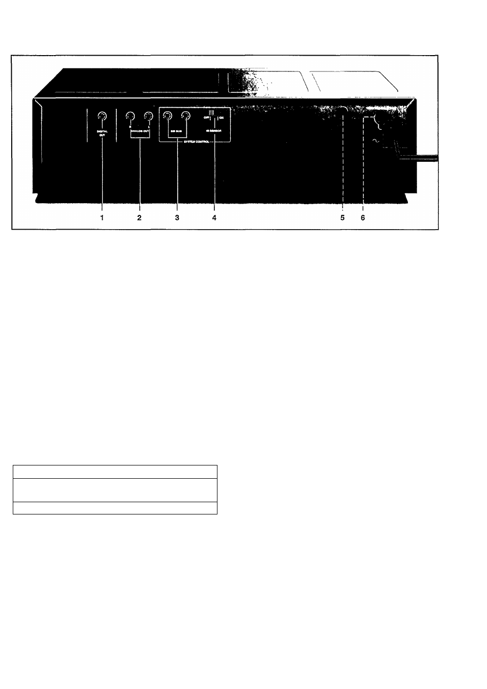
DIGITAL OUT
This output jack supplies a digital signal. This jack must only
be connected to an input which is suitable for this signal.
Use here the cinch lead (b) supplied.
Never connect this jack to the non-digital input of an
receiver or amplifier (such as AUX, CD, TAPE, PHONO, etc!).
ANALOG OUT
This output jack is used to supply non-digital signals to a
receiver^mplifier. Use connection cable (a).
Insert a red plug into the 'R' jack and the other plug into the
'L' jack.
Insert the remaining two plugs into the corresponding jacks
of the CD (or AUX) input of your amplifier.
You can also use the TUNER or TAPE IN connection, but
never the PHONO input!
ESI BUS (Enhanced System Intelligence)
For incorporating the changer in a HiFi system with ESI BUS
connection (e.g. the PHILIPS 900 series) or its own remote
control system.
IR SENSOR OFF ON
Switching the l(nfra) R(ed) SENSOR on and off.
IMPORTANT!
When the changer is incorporated in a HiFi system with ESI
BUS connection, this switch should alwaysbe in the OFF
position.
When the changer is nof incorporated in a HiFi system with
ESI BUS connection, the switch should be in the ON position.
When switching the IR SENSOR on and off, the CD changer
should always be switched off.
5 Power fuse holder (not all versions)
See 'POWER SUPPLY SETTING'.
6 Voltage selector [not all versions)
See 'POWER SUPPLY SETTING'.
Certain versions of this changer are equipped with a voltage
selector (6), which enables you to set the changer to the
correct power supply voltage yourself. When changing the
voltage setting, it is also necessary to change the power
fuse (5) to one of the correct rating:
T200 mA (slow blow fuse) for 110/127 V;
T100 mA (slow blow fuse) for 220 V - 230 V/ 230 V - 240 V.