Mc250-4t/1cxt application connection, Wiring the power inputs, Nection 9 – Interlogix MC250-4T/1CXT User Manual
Page 15: Wiring the power inputs 9
IFS MC250-4T/1CXT User Manual 9
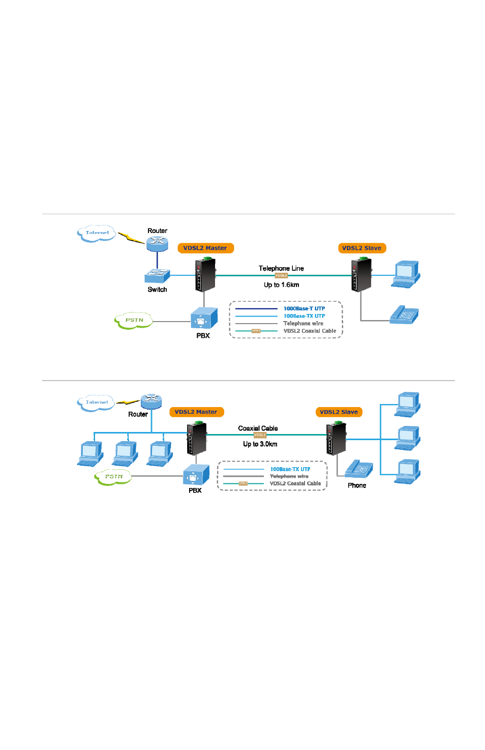
MC250-4T/1CXT Application Connection
Two sets of the MC250-4T/1CXTs could be used to link two
local Area networks that are located in different locations.
Through a normal telephone line or coaxial cable, 100/55Mbps
(RJ-11) or 100/65Mbps (BNC) asymmetric backbone, can be
setup with one media converter in Master (CO) mode and the
other in Slave (CPE) mode.
Figure 3:
MC250-4T/1CXT
VDSL2 (RJ-11) connection
Figure 4:
MC250-4T/1CXT
VDSL2 (BNC) connection
Wiring the Power Inputs
The 6-contact terminal block connector on the top panel of the
MC250-4T/1CXT is used for two DC redundant powers inputs.
Please follow the steps below to insert the power wires.
1. Insert positive / negative DC power wires into the contacts
1 and 2 for POWER 1, or 5 and 6 for POWER 2.
- 600-1053-4 (12 pages)
- NX-590NE (38 pages)
- NX-591NE-GSM (16 pages)
- NX-592E (13 pages)
- Simon XT CDMA Module V4 (9 pages)
- Simon XT GSM Module V4 (10 pages)
- NX-548E (12 pages)
- NX-540E (32 pages)
- D1000 Series (10 pages)
- D1300 Series (11 pages)
- D1315 Series (10 pages)
- D1810 Series (8 pages)
- D2100 Series (10 pages)
- D2300CPS Series (10 pages)
- D7100 Series (8 pages)
- D7400 Series (10 pages)
- D7400RSH Series (10 pages)
- DE7100 Series (9 pages)
- DE7200M Series (8 pages)
- DE7300 Series (9 pages)
- DECT3000 Series (8 pages)
- DED2500 Series (9 pages)
- DT3000 Series (6 pages)
- D1200 Series (8 pages)
- D19100SHR Series (16 pages)
- D9100 Series (12 pages)
- MC251-4P/1CXT (28 pages)
- MC250-4T Series (23 pages)
- MC251-4P/1S (27 pages)
- MC350-4T-2S (32 pages)
- MC352-4P-2S (31 pages)
- MCR200-1T/1CX (25 pages)
- MCR200-1T-1TW (23 pages)
- MC250-1T/1S (24 pages)
- MCR205-1T/1S User Manual (62 pages)
- MCR205-1T/1S Installation Guide (11 pages)
- MC201-1P/1FS (20 pages)
- MC355-1T/1S Installation Guide (13 pages)
- MC350-1T-2S (29 pages)
- MC352-1P/1S (29 pages)
- MC355-1T/1S User Manual (64 pages)
- MCR300-1T/1S (20 pages)
- MCR300-1T-2S (17 pages)
- MCR-R15 (14 pages)