Interlogix Simon XTi GSM Module V4 User Manual
Page 6
6
Simon XT/XTi GSM Module V4 Installation Instructions
LED L5 (yellow)
L5 indicates Z-Wave errors. See Table 5 on page 5 for more
details.
LED patterns for the various module states (modes)
There are three module states, or modes, as described below:
Idle Mode. AC power is OK and the module is not currently
talking to Alarm.com.
L1 - Flashes errors, if any.
L2 - Communication with panel.
L3 - Communication with radio unit.
L4 - Signal level (0 to 5 bars).
L5
– Flashes errors, if any
PowerSave Mode. The module just powered up, AC power is
down, or AC power was recently restored and the battery is
recharging. The module is fully functional and will go into
Connected Mode as soon as a signal needs to be sent. Press
and hold the 5 Key for 10 seconds to switch the module into
Idle Mode and update the signal level reading. The system will
go into Idle Mode every 2 hours to check for any incoming
messages.
L1 - Inactive.
L2 - Communication with panel.
L3 - Same flashing pattern as L2.
L4 - Inactive.
L5 - Inactive
Connected Mode. The module is currently talking to
Alarm.com. The module stays in connected mode for at least
four minutes after reporting an event to Alarm.com, unless the
5 Key is pressed and held for 10 seconds, which will cause the
module to go back to Idle Mode.
L1 - Flashes errors, if any.
L2 - Communication with panel.
L3 - Communication with Alarm.com.
L4 - Alternates two seconds on, then two seconds off.
L5 - Inactive
Sleep Mode. The panel is not connected to AC power, or
there is an AC power failure, and the battery level is low. The
module will connect to Alarm.com to send a signal, but
otherwise is in a state that draws almost no power.
Note: If the HSPA module is powered down for a short period
of time, buffered messages from Alarm.com may be received
when module power is restored.
Improving wireless signal strength
Guidelines for optimal wireless signal strength:
•
Install the module above ground level, as high up as
possible within the structure.
•
Install the module near or adjacent to an outside-facing
wall of the structure.
•
Do not install the module inside a metal structure or close
to large metal objects or ducts.
•
Make sure to follow the antenna positioning guidelines that
are included with the antenna. Certain antennas must be
oriented a specific way in order to receive signals.
•
Upgrade the antenna. If using the 1/4 wave antenna
included with the GSM module, upgrade to a remote cable
antenna. Contact Alarm.com technical support for antenna
options.
As you make changes to the module location or antenna to
improve signal strength, requested updated signal readings to
verify changes. To request an updated reading, press and hold
the “5” key for 10 seconds on the XT or press the ‘Refresh’
button in the “Module Status” menu on the XTi.
Interactive menus
Simon XT panels version 1.3 and up with GSM module v150 &
up or XTi panels with GSM module v151 & up have a special
set of “Interactive Services” menus that can be used to access
information about the GSM module, install or remove Z-Wave
devices and configure or troubleshoot other interactive
features. Refer to Table 6 below for XT menus and Table 7 on
page 8 for XTi menus
Note: If you have an XT 1.2 panel, you can still access some
of the functionality found in the Interactive menus via special
key presses.
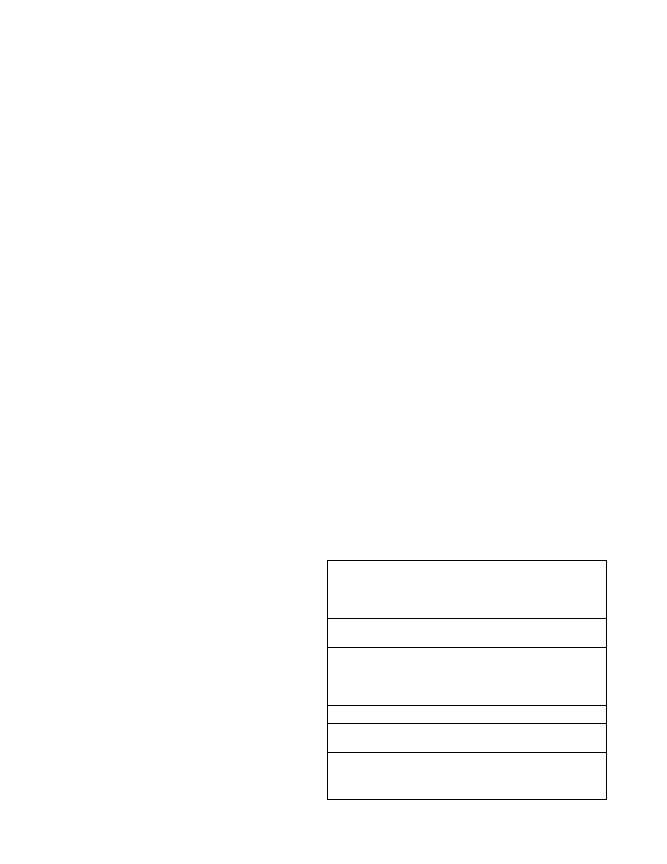
Table 6: Simon XT 1.3 and up Interactive Services menu
Menu
Description
System Programming +
Installer Code
Scroll down to System
Programming. Enter the installer
code and press OK
- Interactive Services
Scroll up to Interactive Services and
press OK
-- GSM Module Status
Scroll down through the various GSM
module information screens
--- Radio
Signal level, connection status,
roaming status, and errors (if any)
--- GSM Freq.
GSM frequency used by the module.
--- GSM Band
By default the module will choose the
best GSM band.
--- Battery
Current battery voltage and AC power
status
--- SN
Module serial number. Needed to