Interlogix Simon XTi GSM Module V4 User Manual
Page 4
4
Simon XT/XTi GSM Module V4 Installation Instructions
Interactive Services menus on the XT and XTi panels. On
Simon XT 1.3 & up panels equipped with GSM modules
version X144 or newer, go to the ‘System Test’ ‘Interactive
Services
’ ‘GSM Module Status’ menu. On the XTi, this
information can be accessed through
‘Programming’
‘Interactive Services’ ‘Module Status’.
See Table 1 below for potential module statues. See Table 3
on page 4 for more information on the referenced LED error
pattern.
Table 1: GSM Module Statuses
Status
Definition
Idle
Most common state
Roaming
Roaming on partner network.
SIM Missing
Same as 2 flashes on LED L1
PowerSave
Mode
AC Power is Down
Registering…
Same as 3 flashes on LED L1
Connection
Error
Same as 4 Flashes on LED L1
Radio Error
Radio is not operating correctly, same as 5
flashes on LED L1
Server Error
Same as 8 flashes on LED L1
Connected
Currently talking to Alarm.com Servers
Connecting…
In the process of connecting to Alarm.com
Updating…
Updating Signal Level
In addition, some of the information can be retrieved on the
Simon XT via long key presses from the keypad. Press and
hold the following panel keys for 10 seconds to display the
given information on the panel display. Most messages are
displayed for under 30 seconds but can be cut short by
pressing the # Key for 10 seconds.
Table 2: Diagnostic key presses
Key
press
Definition
1-Key
10-digit module serial number. This number is needed
to create the Alarm.com customer account.
2-Key
Module firmware version. (e.g. 4152a)
3-Key
15-digit SIM card number.
5-Key
Wireless signal strength level and module status or
error, if any. The panel will display bars for the signal
level (0 to 5) and a number (2 to 31) followed by the
Mode it is in. (See “GSM Module Statuses” on Table 1).
6-Key
Battery voltage as read by the module, to two decimal
places, and the AC power status. (e.g. Battery: 6.79v,
AC Power OK)
8-Key
GSM Frequency used by the module. (“High” = 1900
MHz, “Low” = 850 MHz.) GSM band mode used by the
module. (“Dual Bd.” (Americas only) and “Quad Bd.” (all
countries))
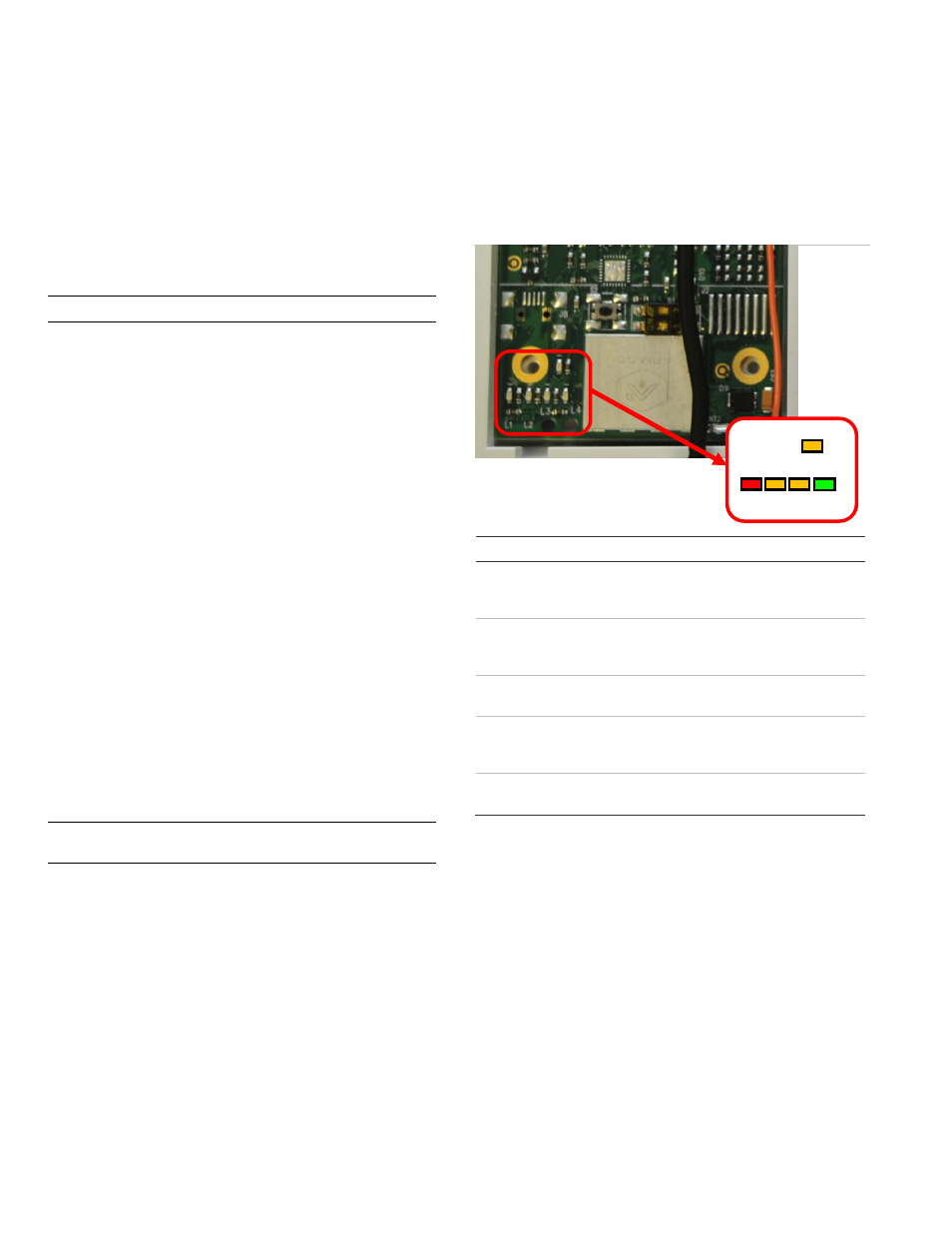
Troubleshooting: LEDs
Status LEDs indicate network and module status. Figure 4
below shows the location of the status LEDs on the GSM
module.
Figure 4: Status LEDs
Table 3 below describes the LED functions.
Table 3: LED functions
LED Function
L1
Error LED. Flashes 1 to 8 times in an 8-second interval to
indicate specific error. See Table 4 on page 5 for errors and
common fixes.
L2
Panel Communication and Z-Wave status messages. Flashes
every time the module communicates with the panel and
flashes in patterns to indicate Z-Wave status.
L3
GSM Communication. Flashes every time the GSM signal level
is checked and when packets are exchanged with Alarm.com.
L4
GSM Signal Level. Flashes 0 to 5 times to indicate signal
strength, or toggles on/off slowly when communicating with
Alarm.com servers.
L5
Z-Wave Error LED. See Table 5 on page 5 for error
descriptions.
LED Details
LED L1 (red)
L1 flashes when there is an error. The number of flashes
indicates the error number. If there are two or more errors at
the same time, the errors will flash one after the other. The
LED will stay off for at least four seconds between errors.
L5
L1 L2 L3 L4