2 baud rate and parity – IC Realtime 1.3 Megapixel 720P HD-AVS IR PTZ Dome Camera User Manual
Page 11
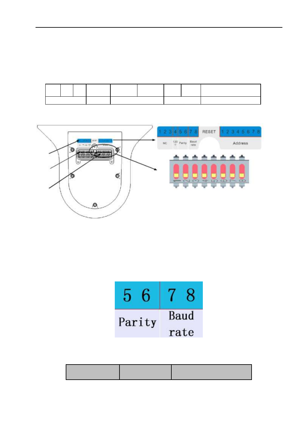
There are two dial switch buttons on the PCB of one side of the speed dome (There are labels.). For
the dial switch button 1-8, 1-
3 is the NC, 4 is the 120Ω resistance setup button, ON is to connect to
120Ω resistance, 5/6 is the party button and 7/8 is the baud rate button. 1 is the lowest bit and the 8 is
the highest bit. You can use them to set speed dome protocol, baud rate, address and etc. See Figure
2-2 . For the protocol dial switch, you can refer to the following sheet. 1 is the lowest bit and the 8 is the
highest bit.
1
2
3
4
5
6
7
8
ON
NC
120
Ω
Parity
Baud rate
Connect to the 120
Ω
After setup, you need to click on-off button or go to the OSD menu to select restart option to
reboot the device to activate new setup.
1
2
ON
OFF
3
1. Address and dial switch button label
2. Protocol dial switch button.
3. Address dial switch button.
Figure 2-2
2.2.2 Baud Rate and Parity
Please note the IR speed dome can automatically recognize the industrial standard protocol,
PELCO-D. PELCO-P. Usually you do not need to set the protocol.
The interface is shown as in Figure 2-3.
Figure 2-3
Please refer to the parity sheet for detailed information.
5
6
Parity
4