Heli-Max HMXM1500 User Manual
Page 2
Before you test and install your governor, if possible, you
should test fly and set up your helicopter to perform the way
you like.
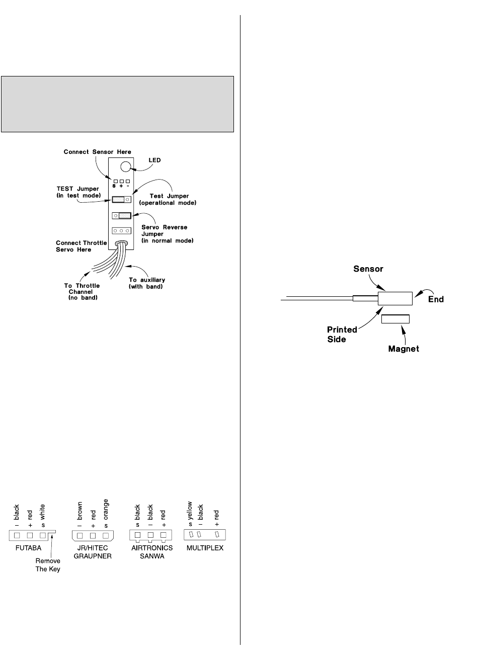
HOOKUP THE GOVERNOR
Your governor comes equipped with Futaba
®
brand “J” style
connectors. If you own a Futaba radio system, proceed to step
1 below. If you own another brand of radio, you may have to
modify the connectors on your governor. See the diagram
below for proper polarities for major radio brand connectors.
Usually, all that is required is to carefully remove the key on the
connectors on the governor with a utility knife so they will fit into
the slot on your receiver. If you’ve modified your connectors,
make certain the wiring order on your governor connectors
and the servo connectors is the same as the wiring order on
the Futaba connector.
Study the diagram carefully. The positive (+) wire is the center,
the negative (-) wire is on the side opposite of the key on the
connector and signal (S) is on the side of the connector nearest
the key. WARNING! Failure to match polarities on any connector
may damage your gyro and will void your warranty.
❏
1. Connect your throttle servo to the bottom output of the
governor.
❏
2. Determine whether you will use a dial to vary your rotor
rpm or a two position switch to switch between a preset high
and low rpm. Connect the lead with a band from the governor
to the channel on your receiver that is operated by the switch or
dial you selected to control rotor rpm (usually Auxiliary 1).
Some pilots with advanced computer radios may choose to use
their programmable mixing and flight conditions to mix preset
rotor rpm with their pitch curves (Idle up 1, Idle up 2). When
different pitch curves are switched on (Idle up 1, Idle up 2), the
preset rotor rpm will be selected without having to adjust an
additional dial or switch.
❏
3. Connect the lead from the governor without the band to
the throttle servo output on your receiver.
❏
4. Connect the governor’s sensor lead to the top output of
the governor.
SET UP AND TEST PROGRAM
Determine The Active Side Of The Magnets
❏
1. Place the test jumper in the test mode on the governor
(refer to the previous diagram).
❏
2. Turn on your transmitter, then your receiver.
❏
3. Place one of the magnets on your workbench. Pass the
sensor over the magnet within a distance of 2mm or less. Note
that the printed side of the sensor, not the end, reads the magnet.
❏
A. If the LED on the governor glows, use a felt tip pen to mark
the upward facing side of the magnet as “active” (mark an “A”).
❏
B. If the LED on the governor does not glow, flip the magnet
over and try again. When the LED glows mark that side of the
magnet as active.
❏
4. Determine and mark the active side of the remaining two
magnets.
Now you’re ready to begin the setup and test program.
Set Up Your Transmitter
❏
1. If your radio has a “hovering throttle trim” (an adjustable
trim operated by a dial that is used to adjust throttle position at
hover only), deactivate or inhibit the trim. This is not to be
confused with your regular throttle trim.
❏
2. Turn your ATV’s at both ends of your throttle servo to
100% (when instructed to do so, you will have to adjust your
throttle linkage mechanically because the ATV’s must be set at
100% for your governor to operate correctly).
Do not mount the governor in your helicopter until instructed
to do so. We recommend setting the governor up on the
bench before you mount it in your helicopter. This will make it
easier to perform the test procedures and give you a better
understanding of how the governor works.
2