Chapter 12 digital outputs & pwm outputs, 1 turbo waste gate control (twg) – Haltech E6X Manual Win Version User Manual
Page 87
E6X Manual
87
CHAPTER 12
DIGITAL OUTPUTS & PWM OUTPUTS
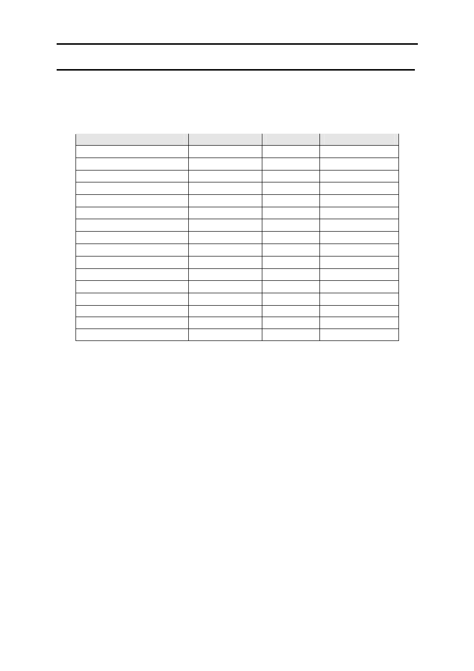
The digital outputs and PWM outputs can be programmed to operate a wide variety of
functions. Some of the functions have restrictions to their operation. The functions and their
restrictions are described in the table below:
Output Description
Digital Out 1–2 PWM 1 – 4
Max #
Turbo Wastegate
N/A
•
2
Bypass Air Control (BAC)
N/A
•
1
Dual Intake Valve
•
•
Unrestricted
Torque Converter Control
•
•
1
Thermofan
•
•
Unrestricted
Intercooler Fan
•
•
Unrestricted
Shift Light
•
•
Unrestricted
Aux Fuel Pump
•
•
Unrestricted
Stall Saver
•
•
1
Staging Signal
•
•
Unrestricted
Turbo Timer
•
•
1
NOS Switch
•
•
1
Anti-Lag Switch
•
•
1
BAC2
N/A
PWM 3 & 4
1
BAC2/BAC Slave
N/A
PWM 3 & 4
1
TPS Switch
•
•
Unrestricted
For installation information regarding any hardware associated with the described output
functions refer to CHAPTER 1 Haltech ECU Installation, p11.
Each individual function and its parameters are described below.
12.1 Turbo Waste Gate Control (TWG)
The turbo waste-gate control function controls a solenoid that bleeds air from the waste-gate
diaphragm preventing the waste-gate from opening.
Period
1 – 50 ms
This sets the period of oscillation of the solenoid. Most
solenoids will operate at around 30Hz, which corresponds to a
period of about 30ms. Enter the desired oscillation period in
milliseconds here.
Use Map
One or Two or Advanced
There are two maps associated with the TWG control function.
Both set the duty cycle driving the solenoid versus engine rpm.
This parameter selects which map the ECU will use to drive the
bleed solenoid.
“One” and “Two” refer to the waste-gate maps one and two
respectively. The “advanced” option refers to conditional use