B.7 ignition outputs, Constant duty, Time – Haltech E6X Manual Win Version User Manual
Page 111
E6X Manual
111
B.7 Ignition Outputs
The ignition outputs of the ECU are designed to provide the appropriate signal to drive an
ignitor. The ECU is capable of driving either smart (Constant duty) or dumb (Constant
charge) ignitors.
WARNING:
UNDER NO CIRCUMSTANCES SHOULD THE IGNITION OUTPUTS
OF THE ECU BE USED TO DRIVE THE COILS DIRECTLY. THE
IGNITION OUTPUTS OF THE ECU ARE INCAPABLE OF SINKING
SUFFICIENT CURRENT TO GENERATE SPARK AND WILL
SIMPLY FORCE THE IGNITION DRIVERS INTO SHUTDOWN
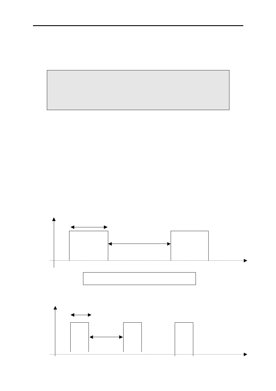
Constant Duty
Constant Duty ignitors contain circuitry that will optimise the dwell for the next ignition and
consequently the ECU only needs to provide a signal that has a constant duty cycle and a
timed edge for ignition. A constant duty ignition signal will appear as below:
The function of the Ignition Module is to trigger the Ignition Coil through the Power
Transistor, which is part of the Ignition Module. There are two main types of ignition
module Constant Dwell and Constant Charge Modules. The Constant Dwell Module (smart)
internally determines coil charge (dwell) time. The ECU therefore triggers the ignition
module using a constant duty cycle with respect to the engine speed (this waveform is
equivalent to the output of a points ignition).
Duty Cycle
30%
Duty
Cycle
30%
GND
+12V
Time
70%
Low RPM
GND
+12V
Time
70%
High RPM
Duty cycle remains constant as RPM increases