Glow engine installation – Great Planes Z526 Zlin Akrobat GP/EP ARF - GPMA1024 User Manual
Page 20
20
o
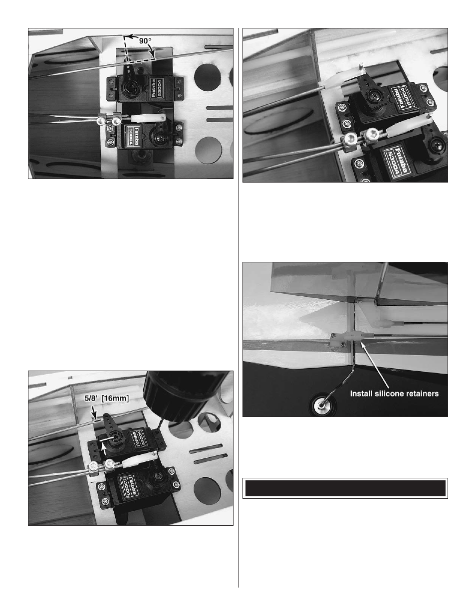
17 . Locate your rudder servo and servo arm that you set
aside earlier . If you didn’t do so already, center the servo
and remove the arm . Set the servo in the servo bay with the
output shaft facing aft as shown . Fit the servo arm so that
you choose the arm that is 90° to the
pushrod . Use a #48
drill bit to drill the outermost hole of the servo arm . Cut off the
unused servo arms .
o
18 . Hold the servo in position so that the rudder pushrod
is directly in line with the outermost hole of the servo arm
or about 5/8" [16mm] from the center of the servo output
shaft . Drill four mounting holes using a 1/16" [1 .6mm] drill bit .
Install the servo using the screws provided with your servo .
Remove the servo and harden the holes with thin CA .
o
19 . Set the rudder at neutral . Mark the rudder pushrod
at the servo arm and bend the rod straight up 90° . Attach
the pushrod to the servo arm using a nylon FasLink . Secure
the servo arm using the attachment screw provided with
your servo .
o
20 . With your rudder servo still centered, adjust the
rudder clevis so that the rudder is at neutral throw . When
you’re satisfied, slide the silicone retainers into position over
the clevises for the rudder, elevator, ailerons, and throttle .
GLOW ENGINE INSTALLATION
This section describes how to install an O .S . FL-70 four-
stroke glow engine . Two and four-stroke engine installations
are similar with the exception of throttle pushrod location .
If you choose to use a two-stroke engine, we recommend
using either the O .S . .46 AX or the O .S . .55 AX . When
installing an engine other than the ones recommended,
choose the throttle pushrod hole in the firewall that best suits
your application .