Final assembly – Great Planes Ultra Sport 1000 Kit - GPMA0425 User Manual
Page 42
D 12 Remove the prop nut and propeller Pop the
spinner backplate loose with a screwdriver and
remove the spacers Remove the engine and mount
in preparation for the next step, but mark the outline of
the engine mount on F-1 with a pencil
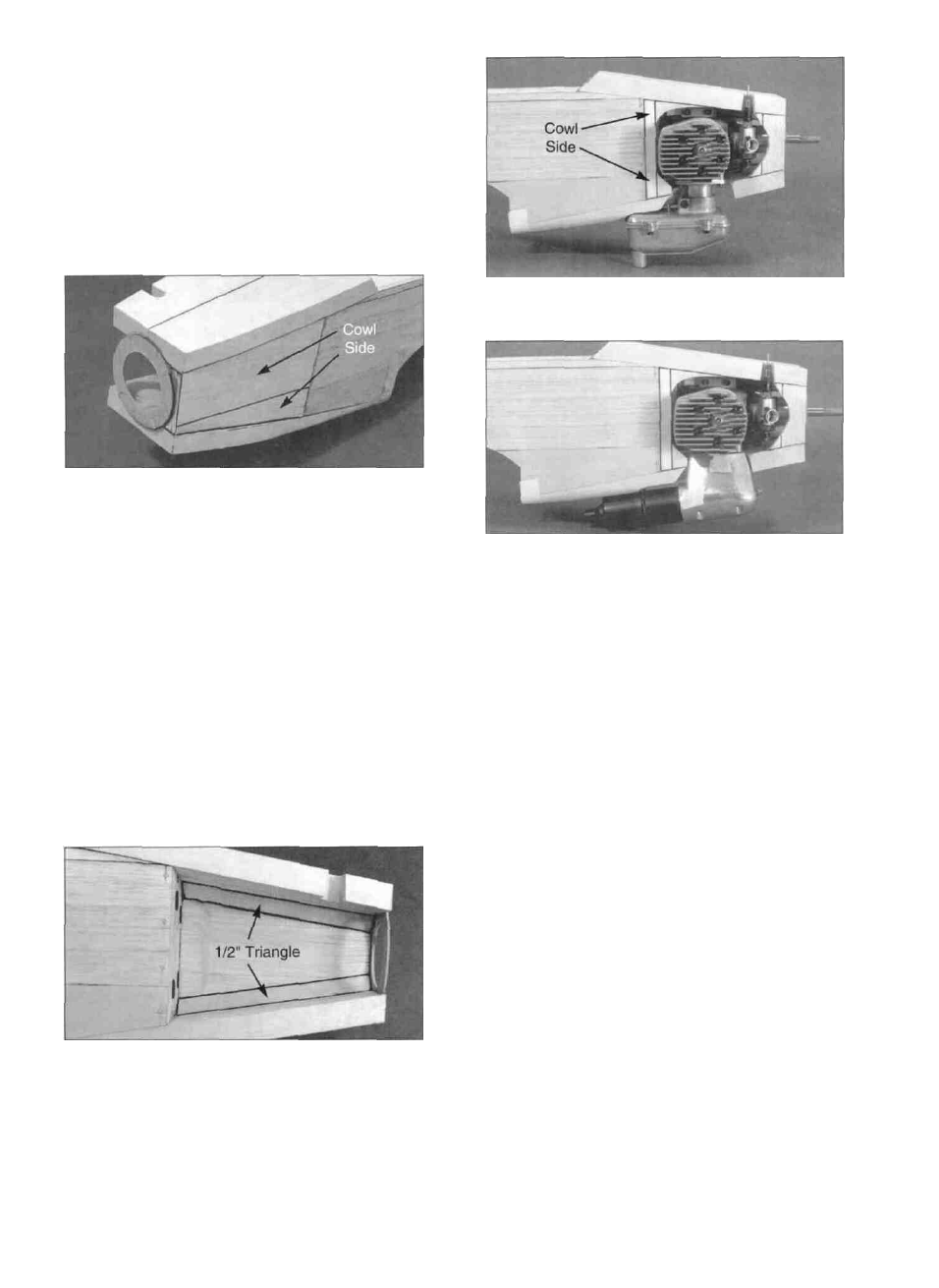
D 13. A 1/2" x 3" x 24" balsa sheet is provided for the
cowl sides From this sheet cut pieces to fit on the
left side of the fuselage between the chin block, top
front block, F-1 and the spinner ring To do this more
easily you may lay the fuse on its left side on top of
the 1/2" balsa sheet and mark the size of the opening
on the sheet (When installing this block, make sure
you stay clear of the engine mount) To allow for
shaping, the cowl side should protrude approximately
1/16" outside of the fuse side at F-1, and should
overlap the spinner ring by about 5/16" Glue the left
cowl side in place.
Photo shows SuperTigre 2500 engine with Supertigre
muffler installed
Photo shows SuperTigre 2500 engine with J-Tec
muffler (for comparison).
D 15. Temporarily re-install the engine and mount;
then, from the remaining 1/2" balsa sheet and 1/2"
balsa triangle, cut pieces to partially fill in the right
side around the engine (The right cowl side should
be essentially the same as the left side, with the
exception of the engine cutout) Also, trim the balsa
as necessary to clear your muffler and throttle
pushrod Cut away just enough of the right cowl side
to allow you to remove and reinstall the engine and
engine mount, and to permit convenient access to the
throttle linkage Typically, you will remove and
reinstall the engine and muffler several times, while
cutting and sanding the cowl side parts for a nice fit
D 16 If you have installed the Supertigre 2500
engine, check the clearance between the large thrust
washer and the inside hole of the 1/16" ply spinner
ring Grind the hole larger if necessary, to provide at
least 3/32" clearance all around.
FINAL ASSEMBLY
D 14 From the 1/2" balsa triangle stock provided cut
lengths to fit in the upper left and lower left corners of
the cowl, between F-1 and the spinner ring Sand
these triangles if necessary to avoid interference with
the engine mount Glue the triangles in place
SAND THE FUSELAGE
NOTE: Some heavy sanding is required to properly
shape the nose area This task can be made much
easier if you use a razor plane and a sanding block
42