Great Planes Super Chipmunk ARF - GPMA1303 User Manual
Page 20
❏
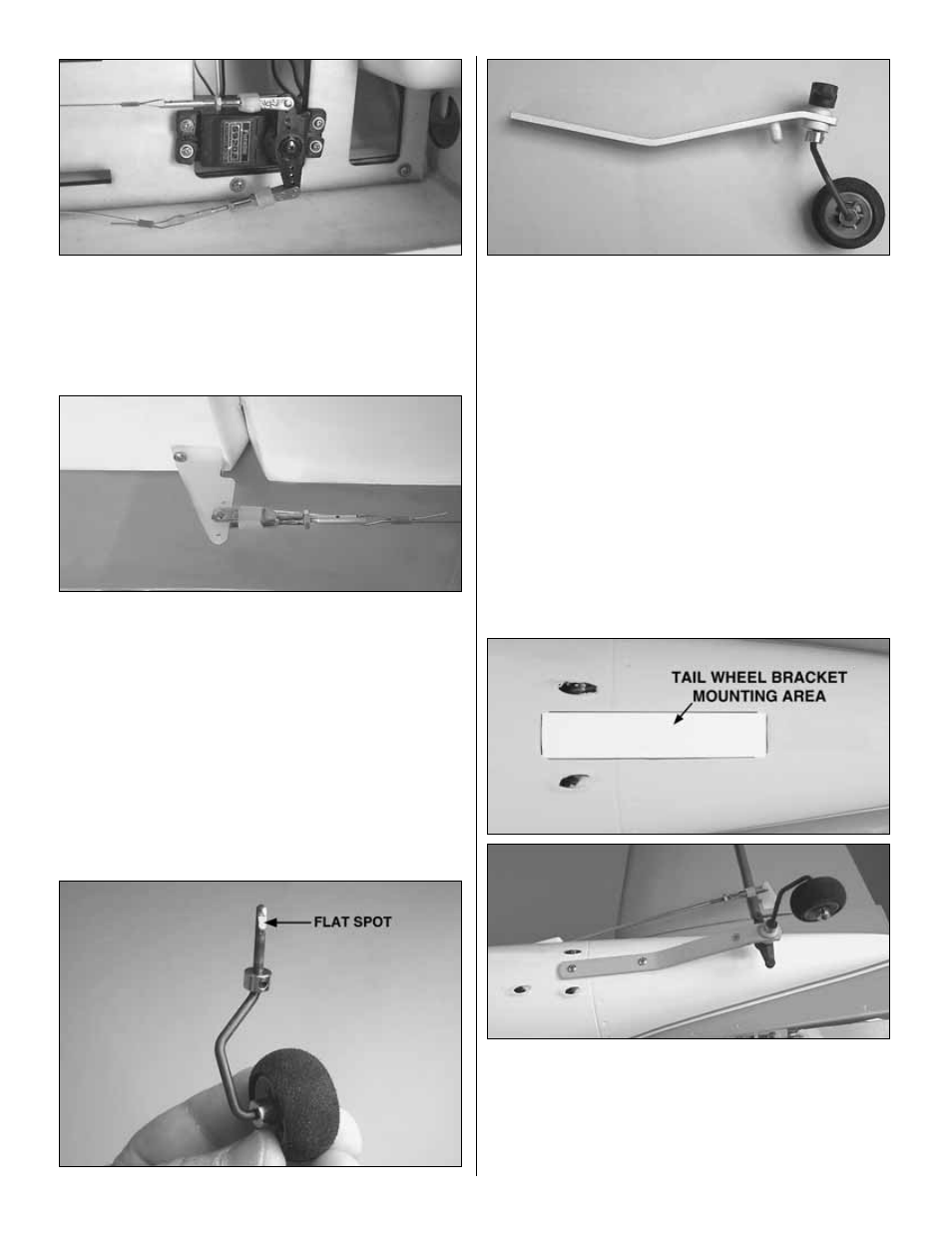
12. Install a wire to each end of the rudder servo arm.
Feed the wire through the outer two tubes until they exit the
fuselage near the rudder.
❏
13. Put together two more sets of threaded brass pull-
pull connectors, clevises and clevis retainers. Install them
into the rudder control horns, one hole in from the end of the
horn. Center the rudder servo and the rudder. Install the
crimp connector onto the wire. Feed the wire through the
connector and back into the crimp connector. Be sure you
have equal tension on both wires, and then crimp the
connector onto the wires with pliers. Adjustment to the wires
can be made by threading the brass connector into or out of
the clevis. Once adjusted, tighten the nut against the clevis.
❏
14. Install the tail wheel and wheel collars to the tail
wheel wire as shown. File a flat spot on the wire for the set
screw in the control arm.
❏
15. On the bottom of the fuselage is a flat area. Place the tail
wheel assembly on this portion of the fuselage and mark the
location of the mounting holes. Drill a 3/32 [2.4mm] hole through
the fuselage on the marks. Insert and remove a #4 x 3/8"
[9.5mm] screw. Apply a couple of drops of thin CA in the holes
to harden the threads. After the glue has hardened mount the
tail wheel bracket with two #4 x 3/8" [9.5mm] screws.
20