Get the model ready to fly, Set the control throws, Check the control directions – Great Planes Edge 540 FlatOuts 3D EP ARF - GPMA1113 User Manual
Page 18
❏
5. Mount the motor and propeller using the hardware and
instructions that came with your motor.
❏
6. Install your ESC as instructed in step 8 of the
“Mount
the Motor & Gearbox” section on page 16.
❏
1. Attach the “loop” side of the hook-and-loop material to
the battery. Mount the battery to the fuselage.
❏
2. For safety, remove the propeller while performing
bench set-up. Once you have finished setting up your
airplane, you can reinstall it.
❏
3. Lower the throttle stick all the way and turn on the
transmitter. Connect your battery to the ESC. If the ESC has
a BEC switch, turn it on.
❏
4. Check all the control surfaces to see if they are
centered. Since you set the center points as you set up the
linkages, they should already be very close. Use the trims
on the transmitter to center the controls.
❏
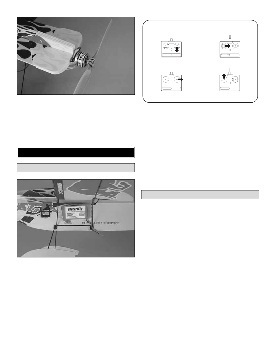
5. Make certain that the control surfaces and the motor
respond in the correct direction as shown in the diagram. To
operate the motor, you may have to “arm” your ESC. Follow
the instructions that came with your ESC to do this. If any of
the controls respond in the wrong direction, use the servo
reversing in the transmitter to reverse the servos connected
to those controls. Be certain the control surfaces have
remained centered. Adjust if necessary.
To simplify setup, the high-rate (3D) control throws for this
model are automatically set by the geometry of the included
hardware. We do recommend, however, that you perform a
quick check as described below to make sure the throws are
set up correctly.
Note: If your radio has the capability, low rates will make it
easier to perform precision aerobatics. We recommend 40%
endpoints for all low rate throws. If your radio does not have
low rates, set up the plane using only the high rate throws.
Additionally, you may want to use the exponential function to
soften the control response around center. This is largely a
matter of personal taste, but helps many pilots balance the
extreme throws needed for 3D flying with the need to make
small corrections when in normal flight.
We recommend setting up your airplane according to the
table shown below
as a starting point. However, setting up
models of this type is largely a matter of personal taste. We
encourage you to tune the throws to your taste as you get
more familiar with the aircraft. Many expert 3D fliers choose
to increase their high rate travel by using higher endpoints.
Set the Control Throws
FULL THROTTLE
RUDDER MOVES RIGHT
LEFT AILERON MOVES DOWN
RIGHT AILERON MOVES UP
ELEVATOR MOVES UP
4-CHANNEL
TRANSMITTER
(STANDARD MODE 2)
4-CHANNEL RADIO SETUP
TRANSMITTER
4-CHANNEL
TRANSMITTER
4-CHANNEL
TRANSMITTER
4-CHANNEL
Check the Control Directions
GET THE MODEL READY TO FLY
18