Radio setup – Great Planes Edge 540 FlatOuts 3D EP ARF - GPMA1113 User Manual
Page 14
❏
1. Remove the stock servo arms from all three of the servos
and temporarily connect the servos and ESC to your receiver.
Power up the system and center all three servos.
❏
2. Refer to the “
Plastic Tree Parts” listing on page 5 and
select the correct offset double-sided servo arm for the
aileron servo you will be using. There are three arms to
choose from:
Servo Arm A: Hitec HS-55, Hitec HS-50, Futaba 3108M
Servo Arm B: Futaba S3103, Airtronics 94091
Servo Arm C: JR 241
❏
3. Install two Z-bend clevises into the
underside of the
offset double-sided servo arm.
❏
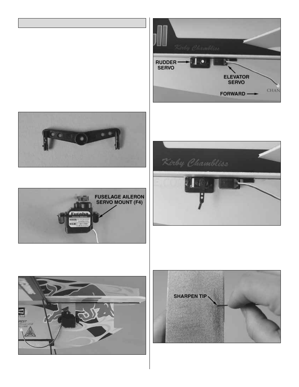
4. Install the servo arm on the aileron servo in the
position shown. Both arms should be offset forward by the
same angle. Glue the aileron servo into a fuselage aileron
servo mount (F4).
❏
5. With the output shaft aft, glue the aileron servo into the
cutout under the wing.
❏
6. Glue the rudder servo into the rear servo mount in the
left side of the fuselage. The output shaft should be forward.
❏
7. Glue the elevator servo into the front servo mount in the
right side of the fuselage. The output shaft should be forward.
❏
8. Select two single-sided servo arms to fit the elevator
and rudder servos you are using. Insert a Z-bend clevis into
the outer hole of each arm. Mount the servo arms so that
they point straight down with the servos centered. Cut a
small hole in the fuselage to allow the elevator servo wire to
pass through to the right side of the fuselage.
❏
9. Using an Easy-Touch
™
bar sander with 220-grit
sandpaper, sharpen the ends of all the 1mm [3/64"] carbon
pushrods. This will make it much easier to install them
through the Z-bend clevises.
Radio Setup
14