Great Planes Edge 540 EP ARF - GPMA1550 User Manual
Page 15
15
direction (use your radio system to test the motor operation).
If the motor is rotating the wrong direction, disconnect any
two of the three motor leads and swap their position. Plywood
clips are included to hold the motor leads away from the
rotating motor. These can be glued anywhere on the motor
box where necessary. Be sure to read the “Lithium Battery
Handling and Usage” section on page 20 of this manual!
❏
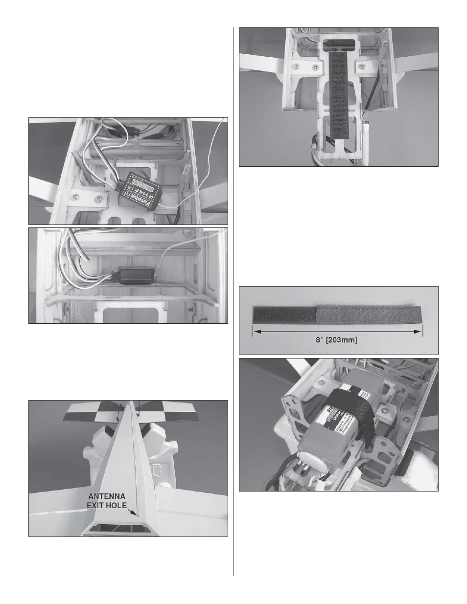
5. Connect the servo leads and ESC to the receiver. If you
are using a 4-channel receiver, you will also need a dual servo
extension or Y-harness for the aileron servos. Cut a piece of
double-sided servo tape to secure the receiver inside the
fuselage. We attached ours to the top of the second former
just behind the battery tray.
❏
6. A small hole just aft of the battery hatch opening is
provided to route the receiver antenna. Trim the covering
from the hole, feed the antenna through it, and tape it to the
underside of the fuselage as shown.
❏
7. Coat the center of the battery tray with epoxy and let it
cure. Apply the “hook” side from the included self-adhesive
hook and loop material to the tray.
❏
8. A strap can be made from the included non-adhesive
hook and loop material for securing the battery pack to the
tray by overlapping the mating ends of the pieces. Apply the
“loop” side of the adhesive hook and loop material to the
battery pack. The strap should be wrapped around the tray
and battery tightly. When you balance the model, the exact
position of the battery pack will be determined. When you
know where the pack will need to be to balance, mark its
position onto the battery tray.