Great Planes Edge 540 EP ARF - GPMA1550 User Manual
Page 13
13
the servo with the servo arm screw. Install a 3-9/16" [90mm]
pushrod into the clevises, center the control surface, and use
2 x 4mm self-tapping screws to secure the clevises to the
pushrod. The screw head should fi t into the recessed hole
in the adjustable clevises as shown (installing the screws
in the wrong direction may not properly tighten the
clevises onto the pushrods).
❏
4. Install the elevator pushrod in the same manner using
a 4-3/8" [110mm] pushrod.
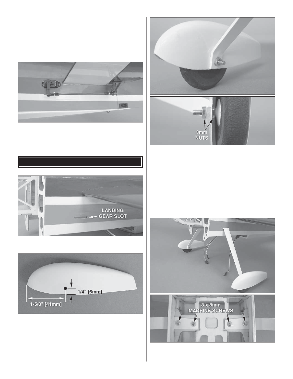
INSTALL THE LANDING GEAR
❏
1. Trim the covering from the landing gear slots in the
fuselage.
❏
2. Measure and mark 1-5/8" [41mm] from the front and
1/4" [6mm] from the bottom of the wheel pants. Drill a 1/8"
[3mm] hole at your marks (or use a reamer) on the inside of
each wheel pant. Accuracy during this step will ensure that
your wheels are centered inside the pants. When drilling the
holes, make a pilot hole with a smaller bit fi rst, then enlarge
the holes to the correct diameter. Be sure to make a left and
right wheel pant!
❏
3. Fit the 3 x 25mm machine screw (axle) through the axle
hole in the wheel and secure the wheel to the axle using a
3mm nut and threadlocking compound. Be sure the nut is
loose enough to allow the wheel to rotate freely on the axle.
Fit the wheel and axle inside the wheel pant with the end of
the screw through the landing gear leg (the tapered sides of
the landing gear legs face the rear of the plane) and install
another 3mm nut with threadlocking compound tightly
against the landing gear leg, securing the wheel pant in place.
The addition of silicone adhesive between the wheel pant and
landing gear leg will help prevent the wheel pant from rotating
on the axle. Repeat this step for the other wheel.
❏
4. Attach the landing gear to the fuselage using four
3 x 8mm machine screws, four 3mm washers, and threadlocking
compound.