Final assembly – Great Planes Christen Eagle ARF - GPMA1217 User Manual
Page 28
❏
4. Mark the two holes in both sides of the landing gear
onto the pants. Note: Although there are molded-in
indentations in both wheel pants for the landing gear, there
is still room for adjustment so it is best to get it right by
aligning the wheel pants in this way.
❏
5. Remove the wheels and pants. Drill 3/32" [2.4mm]
holes at marks you made in both wheel pants. Fit the pants
and wheels onto the gear. If necessary, use #8 flat washers
(supplied) to space the wheels so they are centered in the
pants. Once the wheels have been centered, mount the
pants to the gear with #4 x 1/2" [13mm] screws. Secure the
wheels with 3/16" [4.8mm] wheel collars and 6-32 x 1/4"
[6mm] socket head cap screws. Be certain the screws in the
wheel collars “land” on the flat spots and also be certain to
use a small drop of threadlocker on them. Place a drop of
oil on both sides of both wheels.
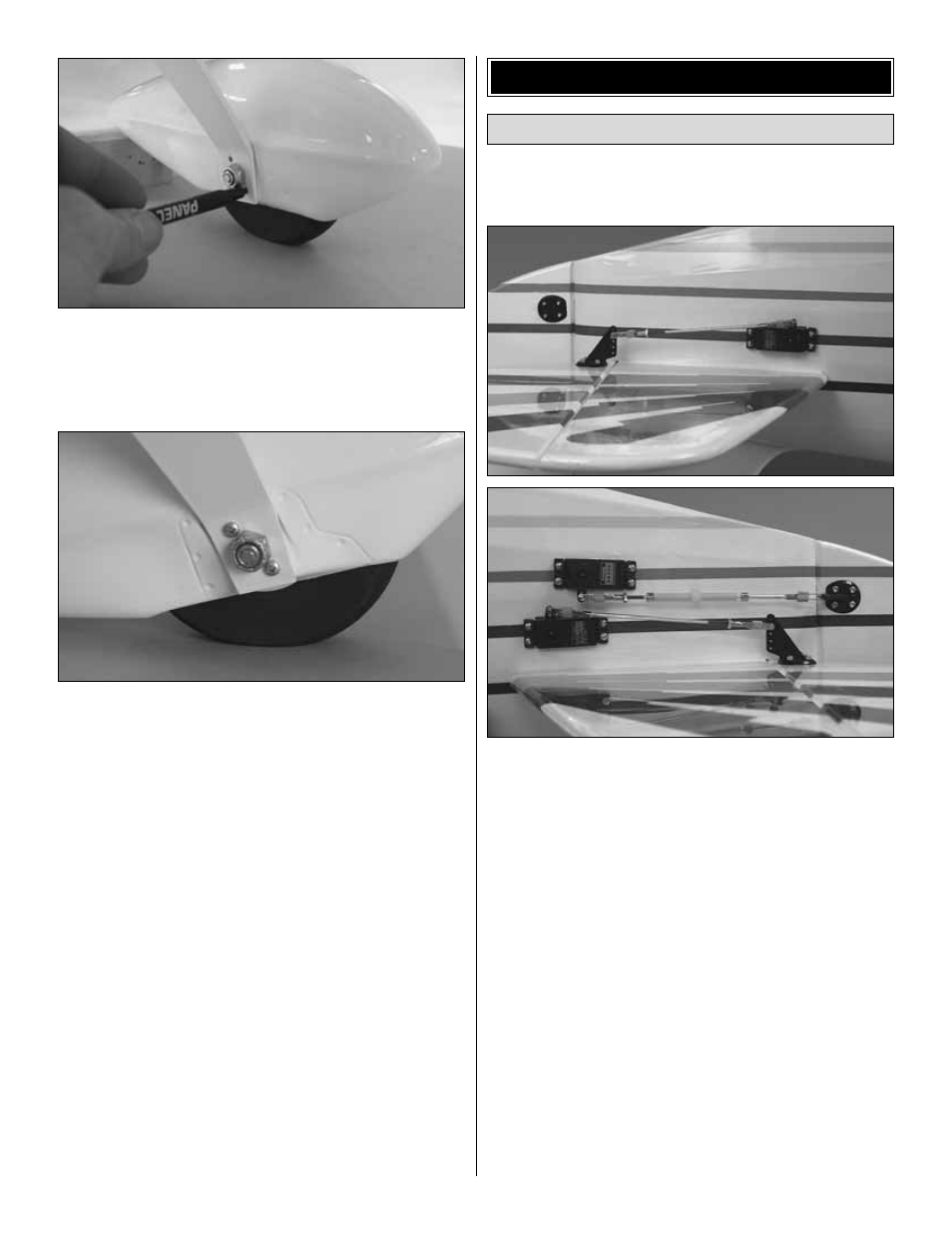
Refer to these photos while mounting the servos and
hooking up the pushrods.
Note: To achieve perfect symmetry in both elevator linkages
the elevator servos move in opposition. For this reason, a
computer radio will be required to electronically mix the
servos so one of them can be reversed. Or, if you do not
have a computer radio, an in-line mixer such as the Futaba
SR-10 servo reverser will be required.
❏
1. The same as was done for the aileron servos, connect
12" [300mm] servo extension wires to each elevator servo
and the rudder servo. Secure the connections with 1-1/2"
[40mm] pieces of heat shrink tubing included with this kit.
❏
2. Mount all three servos in the fuselage using the
previously drilled holes.
❏
3. The same as the aileron pushrods, make two elevator
pushrods from the hardware shown in the previous two photos.
Position the elevator control horns on the elevators so the clevis
holes in the horns align with the pivot point of the elevators.
Mount the horns to the elevators by drilling 7/64" [2.8mm] (or
1/8" [3.2mm]) holes for the screws and using four 4-40 x 3/4"
[19mm] socket-heat cap screws and the nylon mounting plates.
Mount the Servos
FINAL ASSEMBLY
28