Great Planes Christen Eagle ARF - GPMA1217 User Manual
Page 18
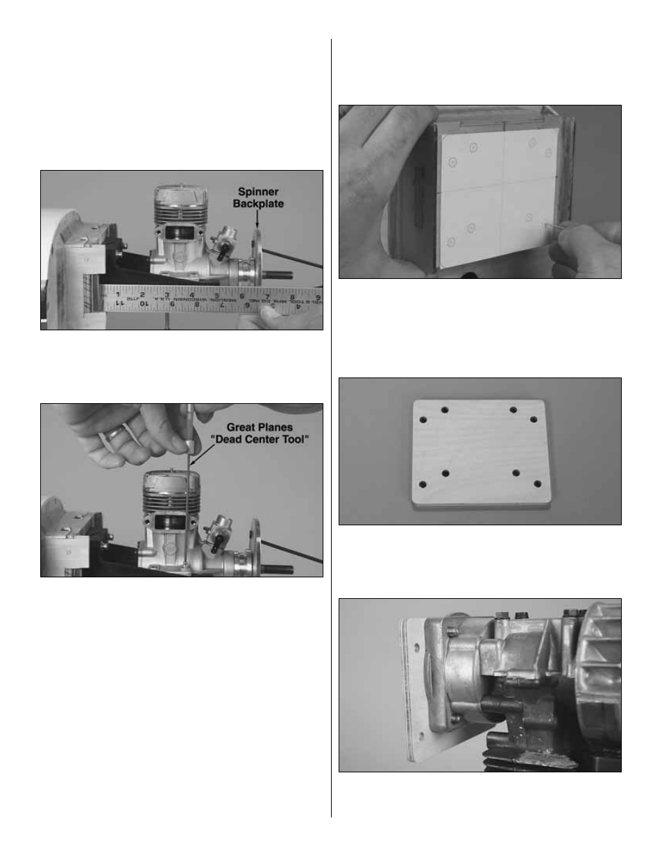
In this step, the engine is shown upright. This is only to
determine the mounting position of the engine on the mount.
Later, the engine will be mounted horizontally.
❏
3. Temporarily mount the engine mount to the firewall
with four 8-32 x 1-1/4" [32mm] socket head cap screws, #8
lock washers and #8 flat washers, but do not fully tighten the
screws. Adjust the mount spacing to fit the engine, then
tighten the screws.
❏
4. Using the appropriate brass spinner adapter that came
with this kit, fit the backplate of the included spinner onto the
engine. Position the engine on the mount so the backplate is
6-1/2" [165mm] from the firewall.
❏
5. Using a Great Planes Dead Center Hole Locator or
another suitable method, mark the location of the holes in
the engine on the mount.
❏
6. Remove the engine and mount from the firewall. Drill
holes through the mount at the marks you made with a #29
drill. Tap 8-32 threads into the holes.
❏
7. Momentarily skip ahead to page 19 and “pin” the
firewall to the fuselage by performing steps 6 and 7. When
complete, return to this page and finish mounting the engine
in step 8 below.
❏
8. Mount the engine mount to the firewall horizontally, but
do not fully tighten the screws. Mount the engine to the
mount with four 8-32 x 1" [25mm] socket head cap screws,
#8 lock washers and #8 flat washers. Center the mount
vertically, then tighten the screws.
MOUNTING A U.S. ENGINES 41CC ENGINE
❏
1. Use a straightedge and a pen to extend the horizontal and
vertical centerlines on the firewall all the way to the edges.
❏
2. Use the U.S. Engines 41cc engine mount template
on page 50 to mark the locations of the four outer holes in
the template onto the firewall. (If making a photo copy of the
template, be certain it comes out the same size as the
template and is not dimensionally distorted.) Drill 19/64"
[7.6mm] holes through the firewall at the marks.
❏
3. Use 3M spray adhesive to adhere the template to a
piece of 1/4" [6.4mm] aircraft plywood. Cut out the plywood
and drill all eight 1/4" [6.4mm] holes. Remove the template
from the plywood (naphtha lighter fluid helps this process).
❏
4. Fuelproof the engine mount with a thin coating of 30-
minute epoxy. After the epoxy hardens, bolt the engine to the
mount with 1/4-20 x 3/4" [19mm] bolts and 1/4" flat washers.
18