Finish the model – Great Planes Spitfire 25 GP/EP ARF - GPMA1478 User Manual
Page 22
The cowl installation is shown on the brushless motor power
system. Installing the cowl over a glow engine is the same.
However, in addition to cutting a cooling hole for the engine
head, you will also need to make a hole for glow plug access, a
hole to access the needle valve, and a cutout for the muffler.
❏
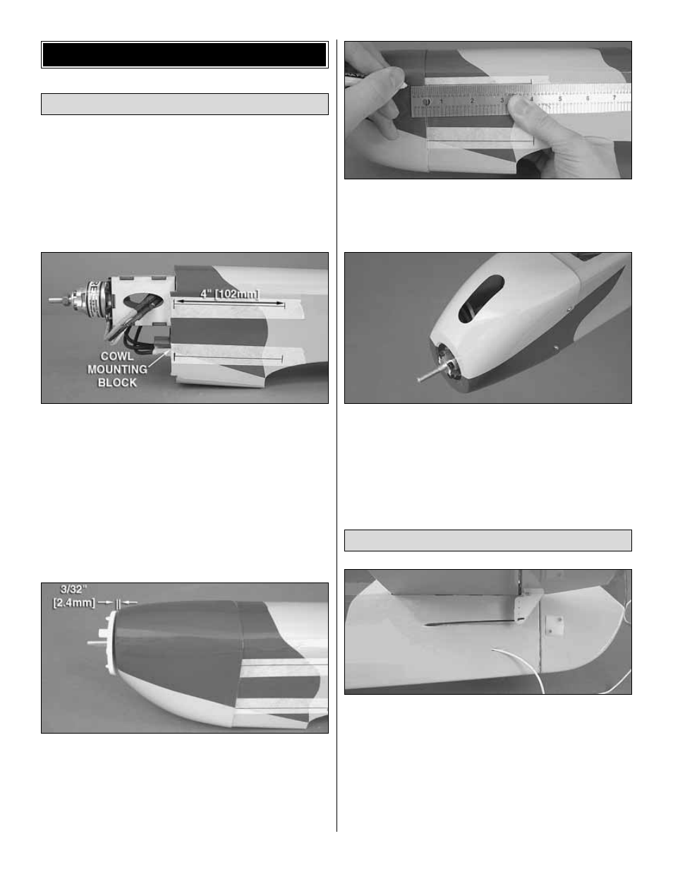
1. Put four pieces of tape at least 5" [127mm] long onto
the sides of the fuse (two per side) evenly spaced apart and
parallel with the fuse center line. Make a mark on each piece
of tape in the center of the cowl mounting blocks that are
glued to the sides of the firewall. Draw a line using a
straightedge 4" [102mm] long from each mark. Mark the end
of each line as shown. These lines will be used to drill the
mounting holes for the cowl.
❏
2. Fit the cowl onto the fuse. Temporarily install the
spinner backplate onto the motor shaft. The backplate may
need to be reamed or drilled out to match the shaft size (1/4"
[6.4mm] for the 35-30-1450 out-runner, 1/4" [6.4mm] for the
O.S.
®
.25 FX glow engine). Position the cowl so that the front
of it is 3/32" [2.4mm] from the backplate, square and is
centered behind it. When satisfied, tape the cowl in place.
❏
3. Measure forward 4" [102mm] from the aft marks on the
tape and mark the cowl for the mounting screw locations.
Drill 1/16" [1.6mm] holes through the cowl and through the
cowl mounting blocks at each mark.
❏
4. Remove the cowl and tape from the fuse. Cut the
necessary holes in the cowl appropriate for your power
system. The picture shows a cooling hole for the brushless
motor setup. Thread a 2mm x 8mm self-tapping screw into
each cowl hole in the fuse and remove it. Apply a couple
drops of thin CA into each hole to harden the wood. When
the CA has fully cured, install the cowl onto the fuse using
four 2mm x 8mm self-tapping screws.
❏
1. The receiver antenna can be taped to the underside of
the fuse. For a cleaner look, we chose to route the antenna
down the inside of the fuse and out the side as shown. To do
this, we used a long scrap piece of pushrod tube we had in
the shop and inserted it through a small hole drilled beneath
the stabilizer. Slide the tube through the hole toward the
front of the plane going through the cutouts in the formers.
When you reach the receiver with the tube, feed as much of
the antenna into the tube as possible, then pull the tube with
the antenna inside of it out through the hole.
Final Assembly
Install the Cowl
FINISH THE MODEL
22